
Apparatus for repeating signal using microstrip patch array antenna

a patch array antenna and antenna technology, applied in repeater circuits, differential interacting antenna combinations, line-transmission details, etc., can solve problems such as discontinuity problems

Inactive Publication Date: 2007-03-15
ELECTRONICS & TELECOMM RES INST
View PDF10 Cites 10 Cited by
  • Summary
  • Abstract
  • Description
  • Claims
  • Application Information

AI Technical Summary

Benefits of technology

[0008] It is, therefore, an object of the present invention to provide an apparatus for receiving a signal from a satellite and repeating the signal to a mobile station in a shadow area by using microstrip patch array antennas.
[0009] In accordance with an aspect of the present invention, there is provided an apparatus for repeating a signal to a mobile station in a shadow area by using a microstrip patch array antenna, the apparatus including: a receiving unit for receiving the signal and amplifying the received signal; a radiating unit for radiating the amplified signal to the shadow area; and a feeding unit for feeding the amplified signal to the radiating unit.

Problems solved by technology

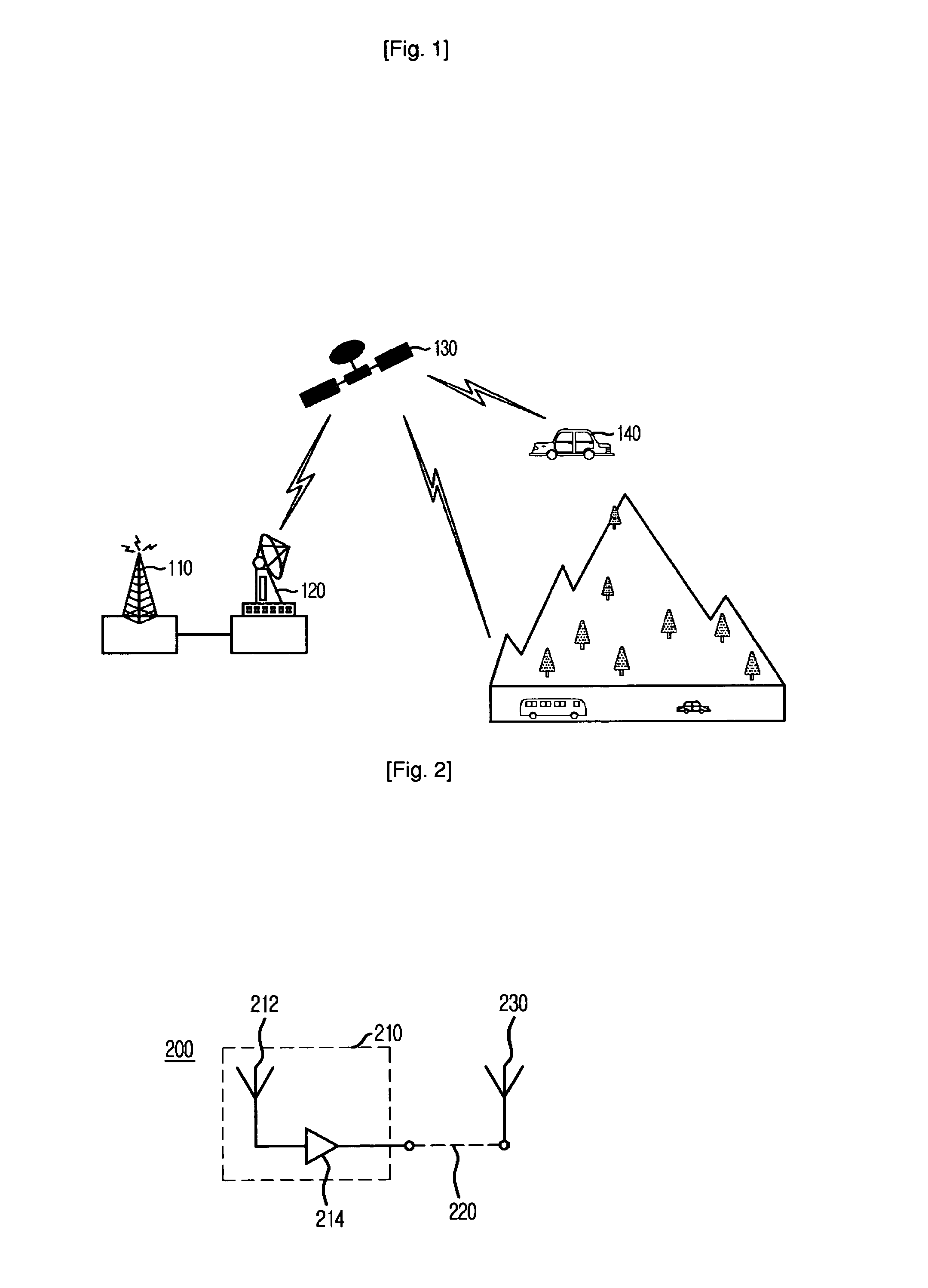
Therefore, the above-described conventional method for receiving the service signal from the satellite 130 causes discontinuity problem.

Method used


Image

  • Apparatus for repeating signal using microstrip patch array antenna
  • Apparatus for repeating signal using microstrip patch array antenna
  • Apparatus for repeating signal using microstrip patch array antenna

Examples


Embodiment Construction

[0018] Hereinafter, an apparatus for repeating a signal using a microstrip patch antenna according to the present invention will be described in more detail with reference to the accompanying drawings.

[0019]FIG. 2 is a block diagram illustrating a satellite repeater in accordance with a preferred embodiment of the present invention.

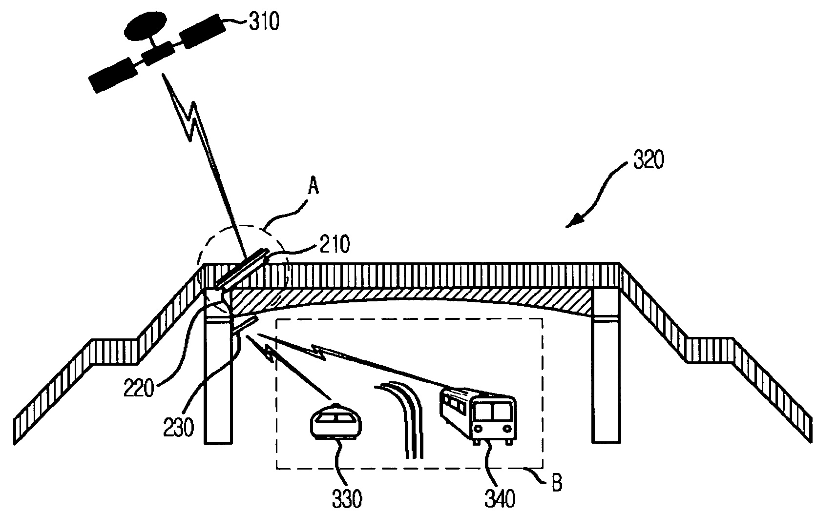
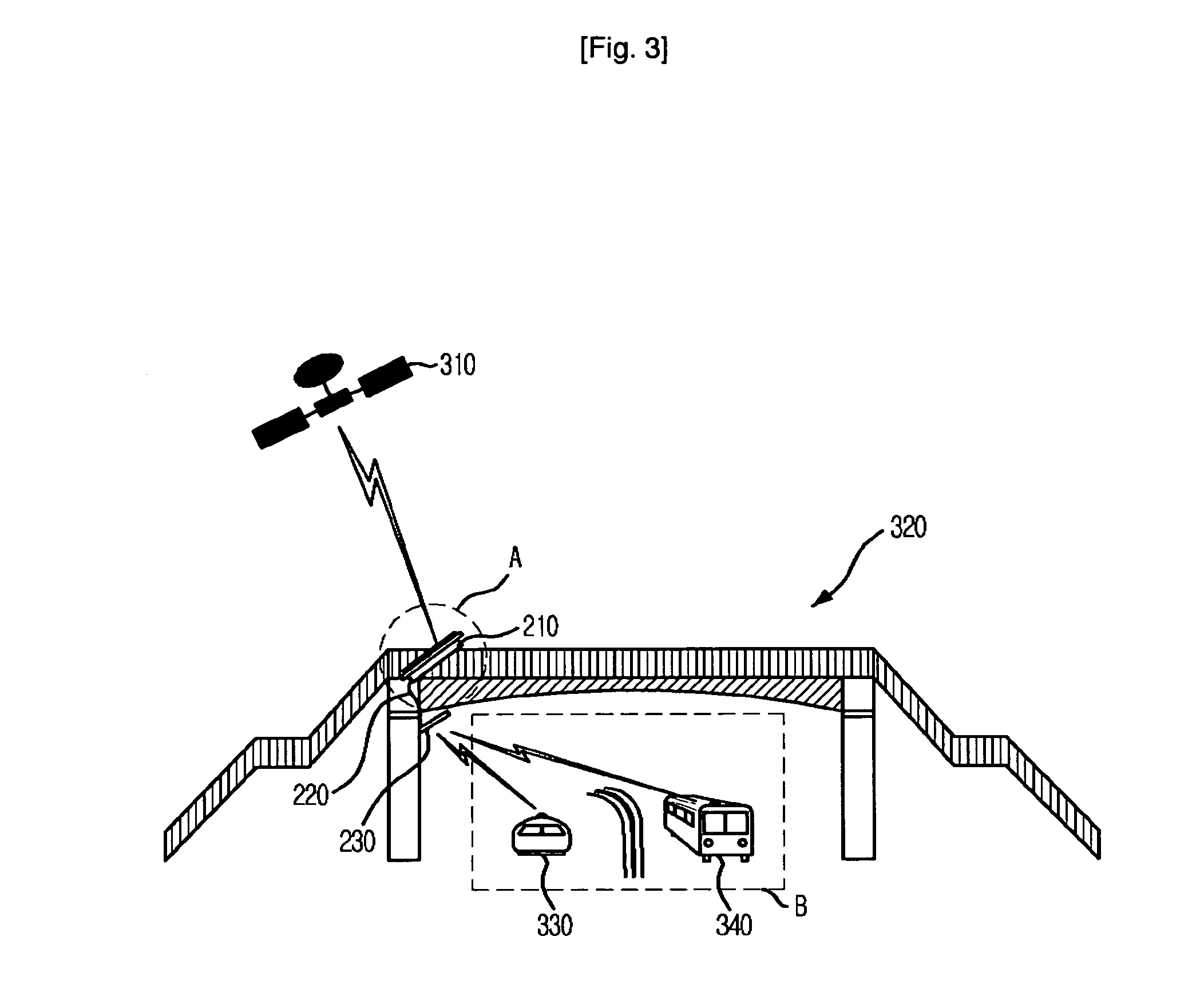
[0020] In accordance with a preferred embodiment of the present invention, the satellite repeater 200 includes a receiving block 210 provided with a receiving antenna 212 and an amplifier 214, a feeding line 220 and a transmitting antenna 230.

[0021] The receiving block 210 is installed outside of a shadow area where a line of sight to a satellite is secured and the transmitting antenna 230 is installed inside of the shadow area. The receiving block 210 and the transmitting antenna 230 are electrically connected through the feeding line 220.

[0022] The receiving block 210 directly receives a signal from the satellite through the receiving antenna 212 wh...


PUM


Abstract

An apparatus for repeating a signal from a satellite using a microstrip patch array antenna is disclosed. The apparatus includes: a receiving unit for receiving the signal and amplifying the receiving signal; a radiating unit for radiating the amplified signal to the shadow area; and a feeding unit for feeding the amplified signal to the radiating unit.

Description

TECHNICAL FIELD [0001] The present invention relates to an apparatus for repeating a signal using a microstrip patch array antenna; and, more particularly, to an apparatus for receiving a signal from a satellite in a shadow area by using a microstrip patch array antenna. BACKGROUND ART [0002] Generally, the user of a mobile station can enjoy desired information such as news, movie and music with a high quality sound through a mobile satellite communication or a broadcasting system when a mobile station directly receives a signal of various information from a satellite transponder in the space without passing through an obstacle of the radio wave. [0003] Moreover, a supply of mobile satellite communication terminal capable of receiving a satellite Internet signal and a satellite broadcast signal in a vehicle, a train, a ship or the like has been rapidly increased. Recently, the mobile communication terminal employs a mobile satellite receiving antenna in the structure of waveguide wi...

Claims


Application Information

Patent Timeline
Patent Type & Authority Applications(United States)
IPC IPC(8): H04B3/36H04B7/14H04B7/185H01Q21/06H01Q21/29H01Q23/00H01Q25/00
CPCH01Q1/007H01Q1/42H01Q21/065H04B7/18515H01Q23/00H01Q25/00H01Q21/29H01Q9/28H04B7/14H04W16/26
Inventor LEE, YONG-MINEUN, JONG-WONLEE, SEONG-PAL
Owner ELECTRONICS & TELECOMM RES INST
Learn More