Torsion vibration damping device

a technology of vibration damping and rotating shaft, which is applied in the direction of rotating vibration suppression, couplings, mechanical equipment, etc., can solve the problems of adverse damping effect, material subject to aging process, adverse damping effect, etc., and achieve good and freely selectable spring and damping properties

Inactive Publication Date: 2007-03-15
MUHR UND BENNDER KG
View PDF0 Cites 9 Cited by
  • Summary
  • Abstract
  • Description
  • Claims
  • Application Information

AI Technical Summary

Benefits of technology

[0005] It is an object of the present invention to provide a decoupling device for an assembly consisting of a driving disc and a drives

Problems solved by technology

The stiffness and thus the natural frequency of the element depend on the ambient temperature, which can adversely affect the damping effect.
In addition, the material of the elements is subject to an aging process.
The material hardens with time, which can result in a further adverse effect on damping.
Furthermore, elastomer materials are suscep

Method used


Image

  • Torsion vibration damping device
  • Torsion vibration damping device
  • Torsion vibration damping device

Examples


Embodiment Construction

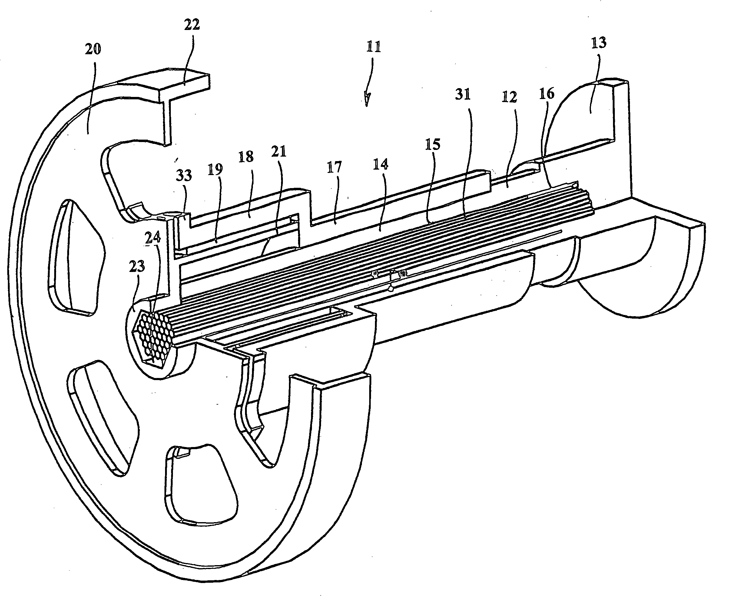
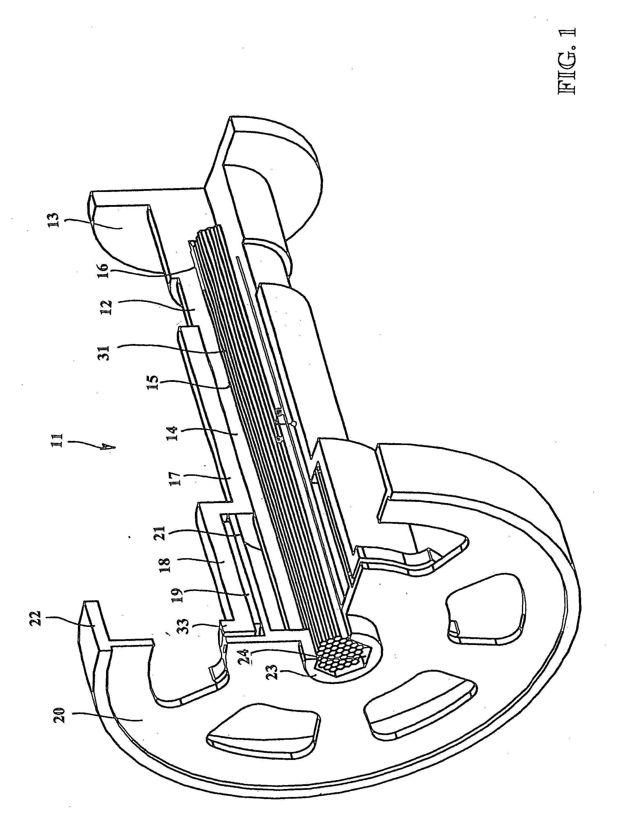
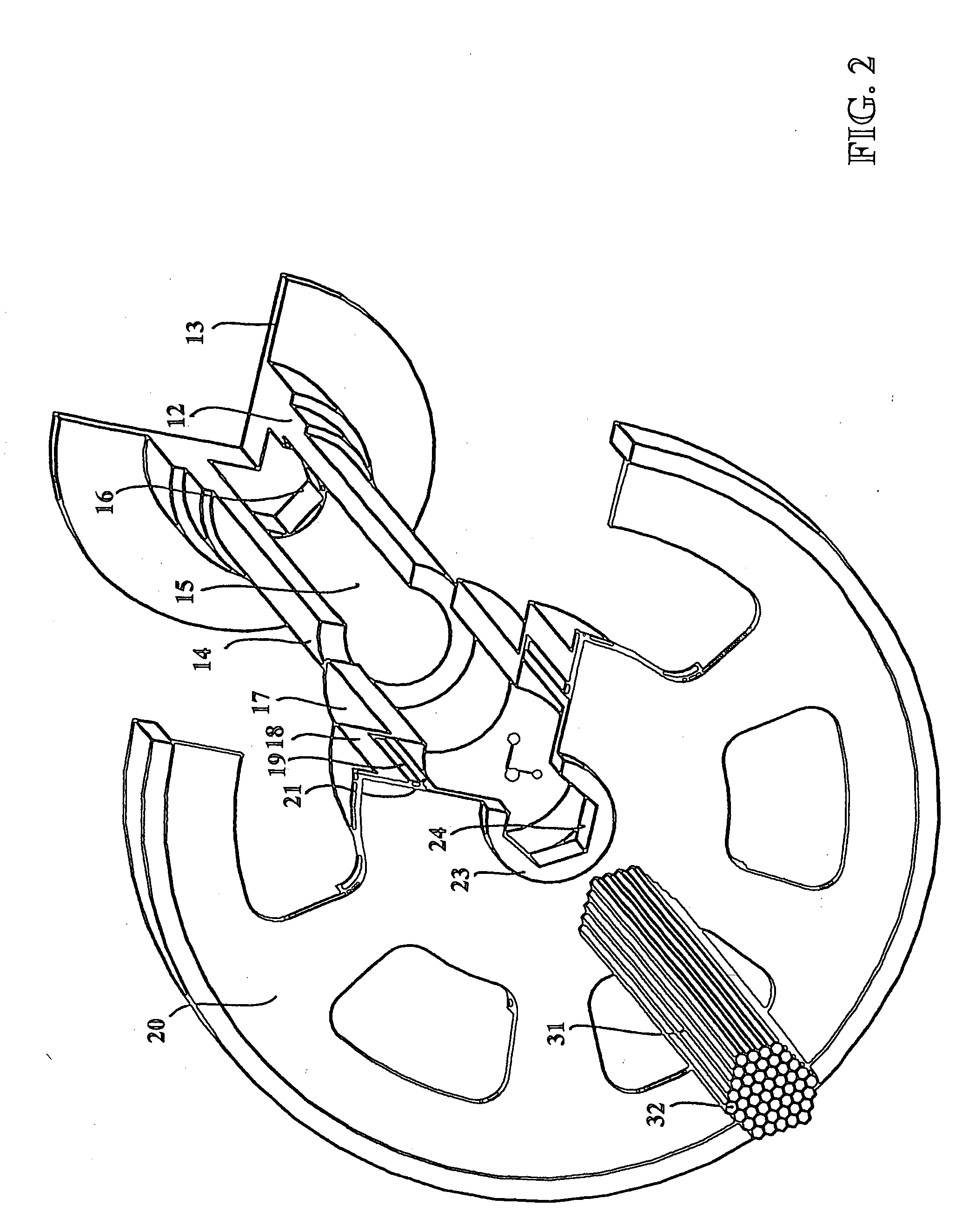
[0027] In all the illustrations, the parts are shown with broken-out sectors of a circumferential angle of approximately 90°. FIG. 1 illustrates an inventive torsion vibration damping device 11 which is connected to the end of a driveshaft 13. The driveshaft 13 is shown in the form of a flange-like widened diameter which is in fact produced so as to be integral with the driveshaft, for example a crankshaft. The free end of the driveshaft 13 is in the form of a hollow shaft 12, and at the inner end of an inner hollow chamber 15, there are arranged form-fitting means 16 provided in the form of a hexagon socket. A bearing sleeve 17 is threaded in a rotationally fast way onto a fixing portion 14 of the driveshaft 13, with the thread pitch relative to the direction of rotation of the driveshaft 13 having been selected to be such that the thread is tightened in operation. The bearing sleeve 17 could also be secured on the fixing portion 14 by means of a press fit or in any other suitable ...


PUM


Abstract

A decoupling device for a driving disc which, for torque transmitting purposes, is connected to a driveshaft via a torsion spring, wherein the end of the driveshaft is provided in the form of a hollow shaft, wherein the torsion spring is bar-shaped and by means of one end is secured in a rotationally fast way in the driveshaft and by means of the other end is secured at the driving disc, and wherein a bearing sleeve is freely rotatably supported relative to the free end of the hollow shaft is firmly connected to the driving disc.

Description

FIELD OF THE INVENTION [0001] The invention relates to a torsion vibration damping device, also called a decoupling device, for a driving disc which, for torque transmitting purposes, is connected to a driveshaft via spring and damping elements. Force can be applied from the driving disc to the driveshaft or from the driveshaft to the driving disc. Suitable driveshafts can be crankshafts or camshafts or internal combustion engines for example, with subsidiary drives being driven by means of the driving disc. Because of the periodic mode of operation of devices such as internal combustion engines, or of piston compressors for example, the shaft ends of such devices are subject to irregularities in respect of angular speed and torque, which can be amplified by vibration and resonance symptoms of the shafts. BACKGROUND OF THE INVENTION [0002] In order to dampen drive irregularities affecting the subsidiary drives, devices incorporate spring and damping elements made of elastomer into d...

Claims


Application Information

Patent Timeline
IPC IPC(8): F16F15/12F16D3/10
CPCF16F15/1421F16F1/16F16F15/1216
Inventor KOBELEV, VLADIMIR
Owner MUHR UND BENNDER KG
Why Eureka
Try Eureka