Control apparatus for an internal combustion engine

a control apparatus and internal combustion engine technology, applied in the direction of electrical control, process and machine control, instruments, etc., can solve the problems of deteriorating the driveability of the vehicle, pressure difference p has not yet reached the lower limit value of normal pressure difference, and the abnormal flow rate of egr of exhaust gas cannot be easily found or recognized by the driver, so as to achieve high reliability the effect of failure determination

Inactive Publication Date: 2007-03-22
MITSUBISHI ELECTRIC CORP
View PDF5 Cites 38 Cited by
  • Summary
  • Abstract
  • Description
  • Claims
  • Application Information

AI Technical Summary

Benefits of technology

[0086] The present invention is intended to solve the problems as referred to above, and has for its object to obtain a control apparatus for an internal combustion engine which is capable of preventing the mis-detection of failure thereby to achieve a highly reliable failur...

Problems solved by technology

If such a state is left, there will arise a problem that a large amount of NOx continues to be generated, but such an abnormal flow rate of EGR of the exhaust gas can not be easily found or recognized by the driver.
However, when the EGR valve 12 is opened and/or closed during the steady-state operation of the engine 1, the torque generated by the engine 1 is varied, thereby deteriorating the driveability of the vehicle.
On the other hand, when ΔP
Accordingly, when a determination is made as to whether the EGR control device is in failure, by detecting the pressure difference ΔP according to the change in the amount of intake air Qa due to the presence and absence of EGR in the deceleration state, it might become, in the worst case, unable to detect the failure state of the EGR control device, or the normal state thereof might be mistakenly detected as a failure state thereof.
As a result, in a device that ma...

Method used


Image

  • Control apparatus for an internal combustion engine
  • Control apparatus for an internal combustion engine
  • Control apparatus for an internal combustion engine

Examples


embodiment 1

[0105] Here, note that the overall configuration of a system related to a first embodiment of the present invention is as shown in FIG. 8, but only a part of failure detection processing executed in an electronic control unit 22 is different from the above-mentioned one.

[0106] That is, as shown in FIG. 8, a control apparatus for an internal combustion engine according to the first embodiment of the present invention includes a throttle valve 7 that is arranged in an intake pipe 3 so as to be opened and closed to adjust an amount of air Qa supplied to an engine 1 through the intake pipe 3, a bypass air amount control section 9 that controls an amount of bypass air Qb flowing while bypassing the throttle valve 7, an EGR (exhaust gas recirculation) tube 11 that serves to recirculate an exhaust gas exhausted from the engine 1 to a portion of the intake pipe 3 downstream of the throttle valve 7, an EGR valve 12 that adjusts the flow rate of EGR Qe of the exhaust gas flowing through the ...

embodiment 2

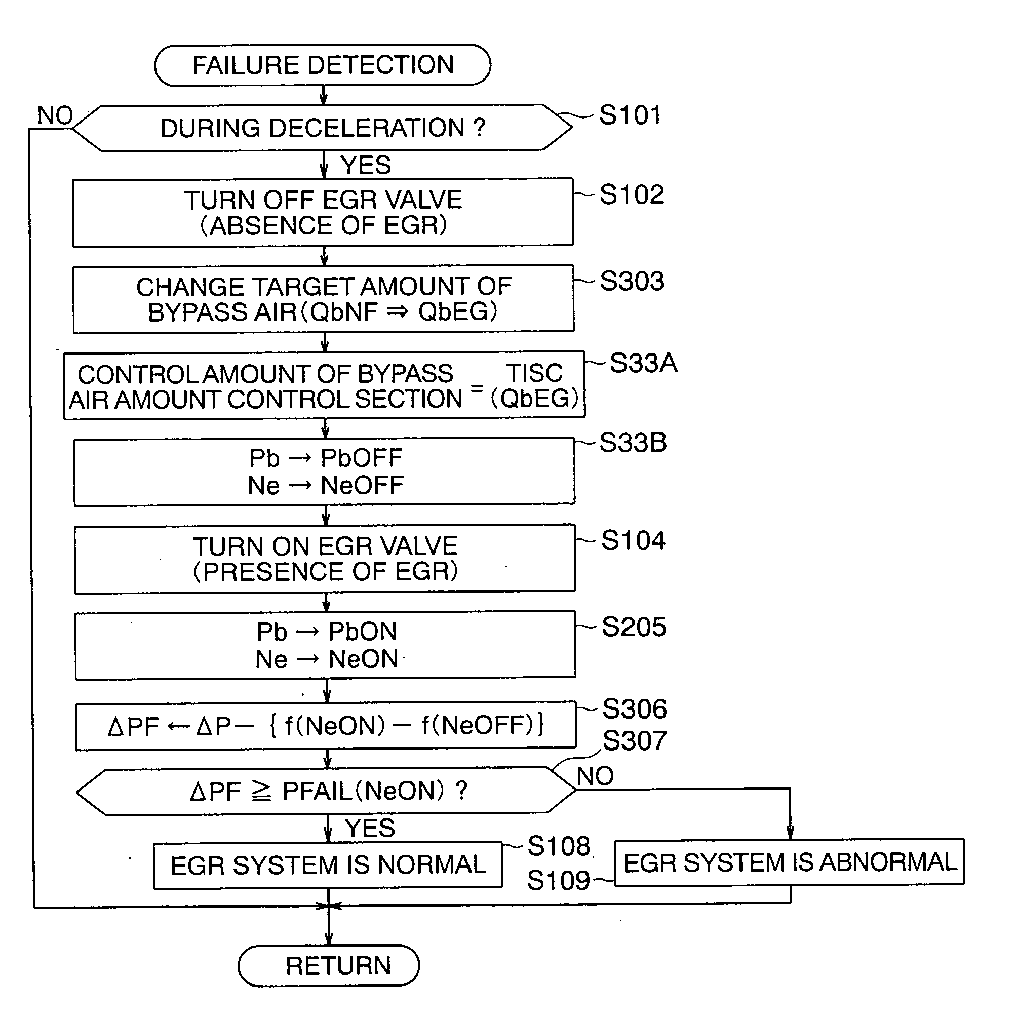
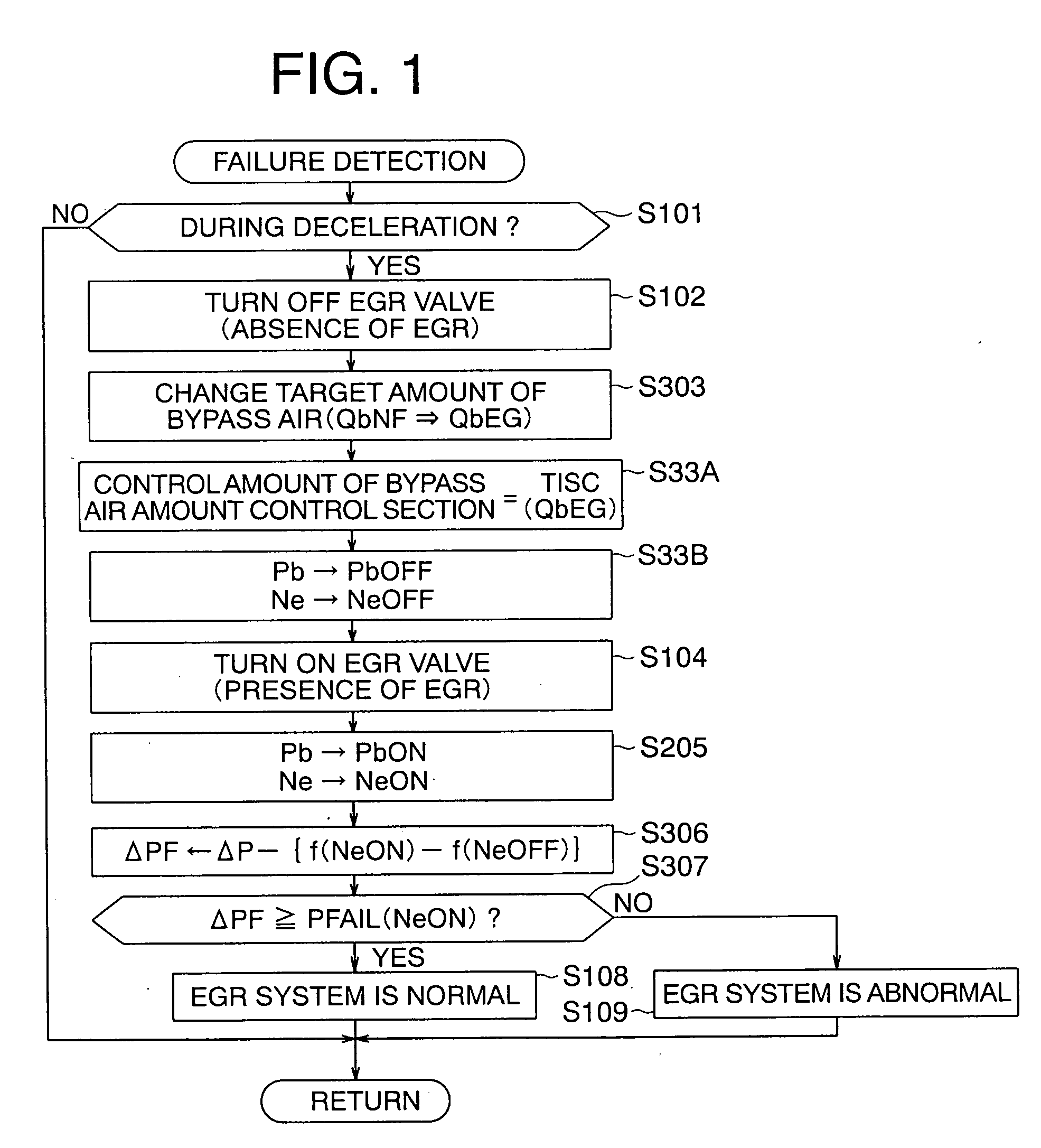
[0154] In the above-mentioned first embodiment (FIG. 1), by only adjusting the bypass air amount control section 9 to the control amount TISC(QbEG) based on the target amount of bypass air QbEG (step S33A), the failure determination condition is assumed to be satisfied (the intake pipe pressure Pb being within the predetermined range), and the pressure difference ΔPF based on the detected value is calculated, but whether the failure determination condition is satisfied may be determined by using a predetermined range calculated based on the number of revolutions per minute of the engine Ne.

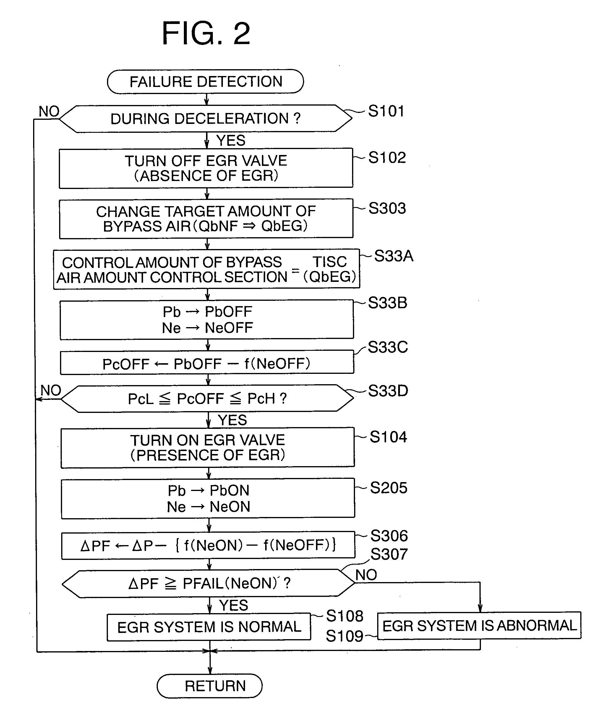
[0155] Hereinafter, reference will be made to a second embodiment of the present invention while referring to a flow chart in FIG. 2 together with FIG. 8.

[0156]FIG. 2 illustrates a failure detection processing operation executed in the electronic control unit 22, in which processes similar to the above-mentioned ones (FIG. 1) are identified by the same symbols as above.

[0157] In this case, the ...

embodiment 3

[0167] In the above-mentioned second embodiment (FIG. 2), when the corrected reference intake pipe pressure PcOFF does not satisfy a permission condition (within a predetermined range) even if the bypass air amount control section 9 is driven by the control amount TISC(QbEG) based on the target amount of bypass air QbEG corresponding to the predetermined state of the intake pipe pressure (the failure determination condition being satisfied), the failure detection processing is terminated (interrupted) at once, but the target amount of bypass air QbEG for EGR failure determination may instead be corrected in a feedback manner until the permission condition is satisfied.

[0168] Hereinafter, reference will be made to a third embodiment of the present invention while referring to flow charts in FIGS. 3 and 4 together with FIG. 8.

[0169]FIG. 3 illustrates a failure detection processing operation executed in the electronic control unit 22, in which processes similar to the above-mentioned...


PUM


Abstract

A control apparatus for an internal combustion engine can compensate for a variation of intake pressure resulting from various factors whereby a failure detection area can be expanded, and false detection can be prevented to enable failure determination for an EGR system with high reliability. The apparatus determines whether a vehicle is decelerating, forcedly opens and closes an EGR valve, and determines whether an EGR control device is in failure by comparing a pressure change index value based on intake pressures upon the forced opening and closing of the EGR valve with a failure determination value. The apparatus adjusts the intake pressure to a predetermined state before the EGR valve is forcedly opened and closed, whereby a failure determination can be always made based on the intake pressure whose variation was compensated for with the intake pressure becoming a predetermined characteristic to the number of revolutions per minute of the engine.

Description

BACKGROUND OF THE INVENTION [0001] 1. Field of the Invention [0002] The present invention relates to a control apparatus for an internal combustion engine (hereinafter referred to as an engine) equipped with a failure detection device for an exhaust gas recirculation control system (EGR system), and more particularly, it relates to a new technique that is capable of preventing the false detection of failure of such an EGR system. [0003] 2. Description of the Related Art [0004] In the past, in engine control apparatuses mounted on motor vehicles or the like, there have been proposed a variety of exhaust gas recirculation (EGR) control devices in which a part of an exhaust gas is recirculated into an intake pipe of an engine so as to reduce the combustion temperature of the engine thereby to suppress NOx components in the exhaust gas (see, for instance, a first patent document (Japanese patent application laid-open No. H8-28364) and a second patent document (Japanese patent applicatio...

Claims


Application Information

Patent Timeline
IPC IPC(8): F02M25/07F02B47/08G01M15/00G06F17/00F02D41/04
CPCF02B77/082F02D41/0055F02D41/221Y02T10/47F02M25/0702G01M15/106F02D2200/0406F02M26/49Y02T10/40
Inventor MIYASAKO, MASAKAZUWADA, KOJISUENAGA, MOTOYASU
Owner MITSUBISHI ELECTRIC CORP
Why Eureka
Try Eureka