Method of electroplating printed circuit board using magnetic field having periodic directionality

a technology of periodic directionality and electroplating method, which is applied in the field of electroplating printed circuit boards (pcb) using a magnetic field having periodic directionality, can solve the problems of unidirectional lorentz force in the plating device, inability to fill the via hole having a high aspect ratio or realizing inability to meet the requirements of a uniform plating layer, so as to reduce the variation of plating and increase the flow of electrolyte solution

Inactive Publication Date: 2007-03-22
SAMSUNG ELECTRO MECHANICS CO LTD
View PDF3 Cites 11 Cited by
  • Summary
  • Abstract
  • Description
  • Claims
  • Application Information

AI Technical Summary

Benefits of technology

[0013] Leading to the present invention, intensive and thorough research on electroplating methods using a magnetic field, carried out by the present inventors, aiming to overcome the problems encountered in the prior art, resulted in the finding that the direction of the magnetic field is periodically changed to control the flow direction and density of the plating ion, thereby increasing flow of the electrolyte solution and decreasing the variation in plating, leading to the formation of a uniform plating layer.
[0014] Accordingly, one aspect of the present invention is to provide a method for electroplating on a PCB using a magnetic field having periodic directionality, which can prevent aging of a plating solution and can make the ionic concentration of the plating solution uniform without the use of an additional external liquid flow device.

Problems solved by technology

Under these circumstances, conventional plating techniques are incapable of fill-plating a via hole having a high aspect ratio or of realizing a uniform plating layer for the formation of a metal wire having a fine pattern.
In light of this, although Japanese Patent Laid-open Publication Nos. Hei. 7-169714 and 5-78885 disclose an electroplating method using a magnetic field, aging of the plating solution and non-uniform ionic concentration thereof are caused by the application of a magnetic field having a fixed flow direction, undesirably resulting in non-uniform plating.
However, in the case of the magnetic field application electroplating method using the plating device of FIG. 2, because the direction of the generated magnetic field is fixed, unidirectional Lorentz force in the plating device results.
Accordingly, the fixed flow direction of the magnetic field may negatively affect the ionic concentration gradient (FIG. 3).

Method used


Image

  • Method of electroplating printed circuit board using magnetic field having periodic directionality
  • Method of electroplating printed circuit board using magnetic field having periodic directionality
  • Method of electroplating printed circuit board using magnetic field having periodic directionality

Examples


example 1

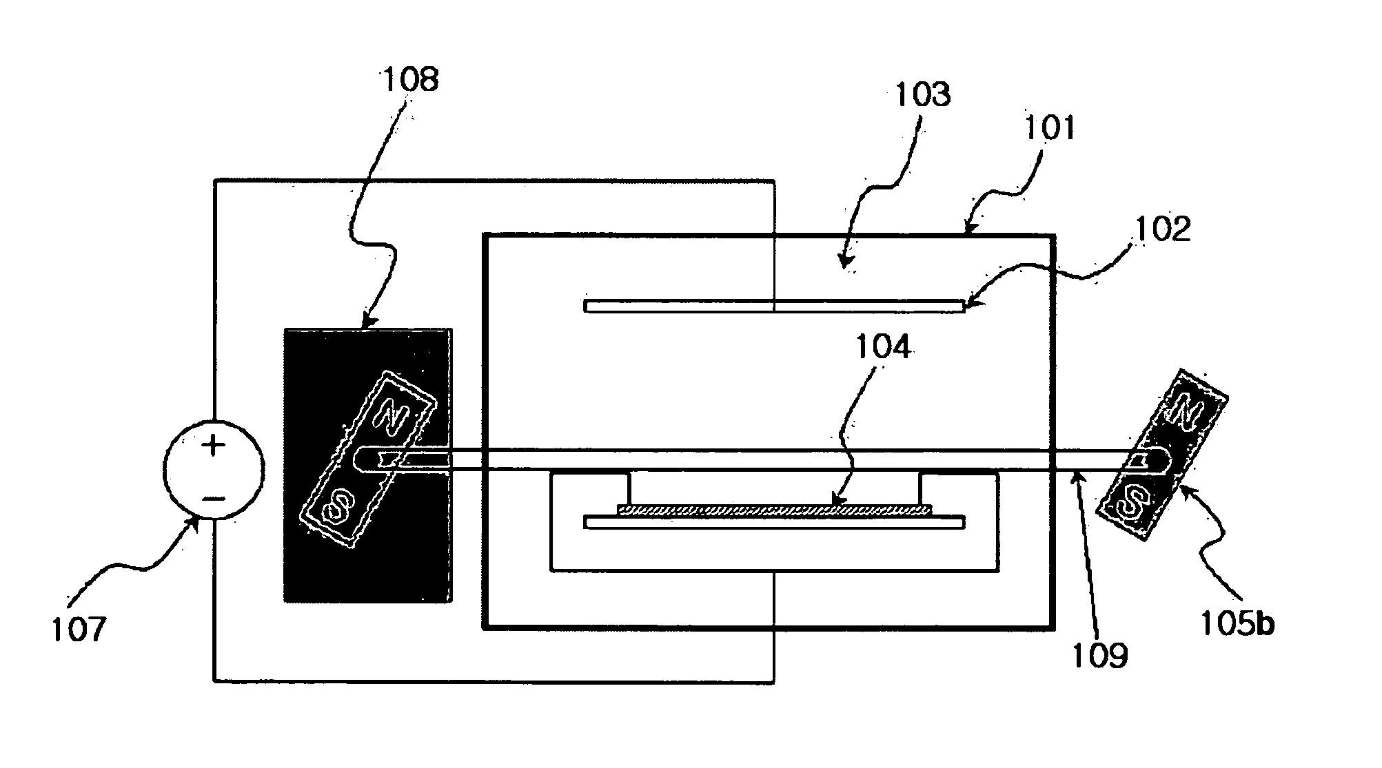
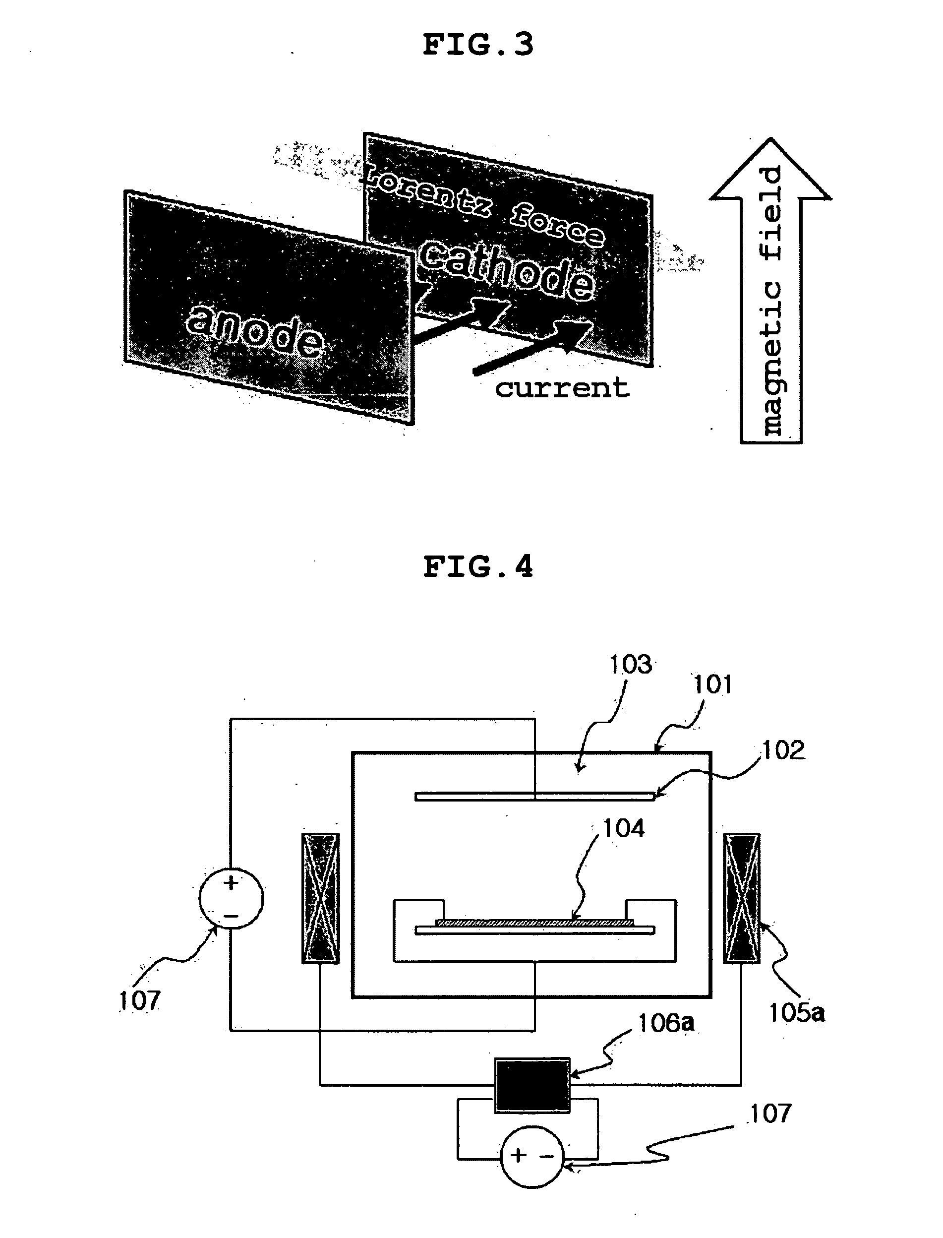
[0051] In an electroplating device of FIG. 4, a copper plating solution, comprising 50 g / l sulfuric acid, 200 g / l copper sulfate, 50 ppm chlorine, and various additives, that is, 100 mg of a carrier, 2.5 mg of a brightener, and 7.5 mg of a leveller, was used as an electrolyte solution, and conditions shown in Table 1 below were applied, thus forming an electroplating layer on a PCB.

[0052] To this end, as the PCB, a 6 cm (width)×6 cm (length) sized test sheet having a via hole having a diameter of 50 μm and a pattern of 40 μm was used. The test sheet was sonicated for 5 min to remove organic material from the substrate and then washed with 0.1 N sulfuric acid for 30 sec and subsequently with distilled water to increase affinity with the plating solution, before copper electroplating. As such, the above pretreatment procedure was the same as a plating pretreatment process typically known in the art.


PUM

PropertyMeasurementUnit
diameteraaaaaaaaaa
diameteraaaaaaaaaa
diameteraaaaaaaaaa

Abstract

Disclosed is a method of electroplating a printed circuit board using a magnetic field having periodic directionality, in which the printed circuit board is electroplated using a magnetic field that is generated substantially perpendicular to a current direction and that has periodic directionality between a forward wave and a reverse wave. According to the method of the present invention, since the magnetic field having the periodic directionality is used, the aging of the plating solution may be prevented and the ionic concentration thereof may be made uniform even without the use of an external liquid flow device, and as well, the substrate may be uniformly plated.

Description

BACKGROUND OF THE INVENTION [0001] 1. Field of the Invention [0002] The present invention relates to a method of electroplating a printed circuit board (PCB) using a magnetic field having periodic directionality. More particularly, the present invention relates to a method of electroplating a PCB, capable of realizing uniform plating while preventing the aging of a plating solution without the need for an additional external liquid flow device, using a magnetic field which is generated substantially perpendicular to the current direction and which has periodic directionality between a forward wave and a reverse wave. [0003] 2. Description of the Related Art [0004] Generally, PCBs for use in the operation of electronic products are produced through numerous fabrication processes comprising complicated process steps. Among the fabrication processes, a plating process, that is, a metallization process, plays an important role in the application of current and voltage to electronic devi...

Claims


Application Information

Patent Timeline
Patent Type & Authority Applications(United States)
IPC IPC(8): C25D5/00
CPCH05K3/241C25D5/006H05K2203/104C25D5/007H01L21/288
Inventor CHUNG, TAE JOONKO, YOUNG GWANPARK, YOUNG GEUNPARK, JI YEON
Owner SAMSUNG ELECTRO MECHANICS CO LTD
Why Eureka
Try Eureka