Illuminating device, and light source unit incorporating same

Inactive Publication Date: 2007-03-22
MINEBEA CO LTD
View PDF4 Cites 53 Cited by
  • Summary
  • Abstract
  • Description
  • Claims
  • Application Information

AI Technical Summary

Benefits of technology

[0010] Consequently, lights emitted from the plurality of LEDs can be efficiently condensed by the light condensing means thereby enhancing the front brightness for the illuminating device. Since a driving circuit to generate a high voltage is not required, and since heat dissipation measures can be simplified due to reduced heat value from the light source, the illuminating device can be reduced in dimension and cost. Since the light condensing means is constituted by Fresnel lenses, its thickness can be reduced thus contributing to downsizing, and its F-value can be set to 1 or smaller thus improving the condensing efficiency and theref

Problems solved by technology

Also, a discharge lamp generates a large amount of heat making it necessary, in many cases, to take measures to deal with the heat, for example, installation of a cooling fan, and at the same time power consumption reduction is a difficult issue to address.
Due to

Method used


Image

  • Illuminating device, and light source unit incorporating same
  • Illuminating device, and light source unit incorporating same
  • Illuminating device, and light source unit incorporating same

Examples


Embodiment Construction

[0019] A preferred embodiment of the present invention will hereinafter be described with reference to the accompanying drawings.

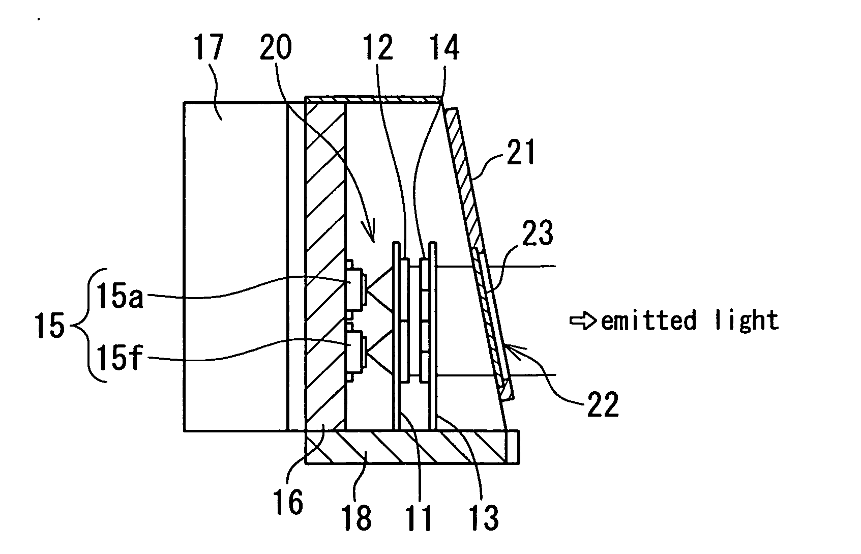
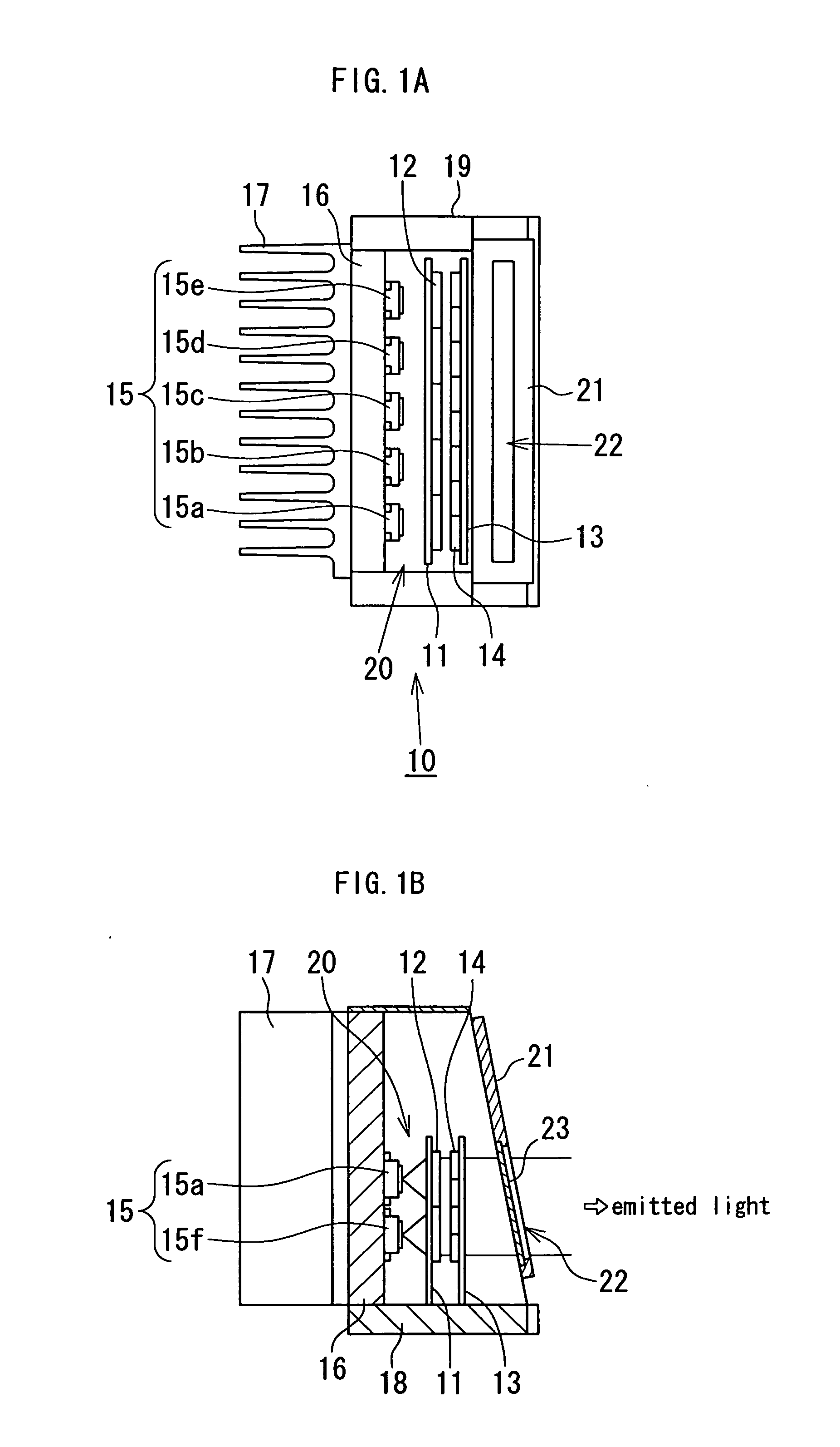
[0020] Referring to FIGS. 1A and 1B, a light source unit 10 of the present invention includes a housing 19, a liquid crystal panel 23 disposed in front of the housing 19, and an illuminating device 20 disposed inside the housing 19 so as to be located behind the liquid crystal panel 23. The liquid crystal panel 23 is a well known light modulating means constituted such that liquid crystals are sandwiched between a pair of substrates working as electrodes. In the light source unit 10 described above, image information produced by the liquid crystal panel 23 is illuminated from behind by the illuminating device 20 so as to be projected onto a projection optical system (not shown) through an aperture 22 formed at a light shielding plate 21.

[0021] According to the present embodiment, the illuminating device 20 includes, as shown in FIGS. 1A and 1B, a surface...


PUM


Abstract

There is provided an illuminating device which includes: a surface light source including a plurality of light emitting diodes disposed two-dimensionally; a light condensing means comprising a plurality of Fresnel lenses which are disposed corresponding to respective light emitting diodes, and each of which converts a light from each light emitting diode into a substantially collimated light; and a light diffusing means disposed at the stage consequent to the light condensing means, and including a plurality of Fresnel lenses which have a smaller diameter and are arranged in a higher density than the Fresnel lenses of the light condensing means. The illuminating device is adapted to emit a highly bright light with excellence in brightness uniformity, and a light source unit incorporating the illuminating device disposed behind a liquid crystal panel is suitably used in an HUD.

Description

BACKGROUND OF THE INVENTION [0001] 1. Field of the Invention [0002] The present invention relates to an illuminating device, and a light source unit incorporating an illuminating device, and more particularly to a light source unit suitable for use in a head-up display. [0003] 2. Description of the Related Art [0004] In recent years, a head-up display (hereinafter referred to as HUD as appropriate) has been increasingly used in aircrafts and automobiles, which presents image information superposed on a viewer's outside scene ahead of the aircrafts or automobiles. FIG. 5 is a schematic view of a typical on-vehicle HUD system, where an HUD 100 includes a light source unit 110 and a projection optical system 104 which are disposed inside an instrument panel 101. The light source unit 110 usually includes a light-transmissive liquid crystal panel 103 and an illuminating device 102 disposed behind the liquid crystal panel 103. Image information O produced by the light source unit 110 is ...

Claims


Application Information

Patent Timeline
IPC IPC(8): G02F1/1335
CPCG02B2027/0118G02F1/133611G02B27/0101G02B5/02G02F2001/133607G03B21/16G03B21/2033F21V5/045G02B3/0056F21V5/007F21Y2101/02G02F1/133603G02B3/08F21Y2115/10G02F1/133607
Inventor KITAMURA, ATSUSHIKUNIMOCHI, TORU
Owner MINEBEA CO LTD
Why Eureka
Try Eureka