Eureka AIR delivers breakthrough ideas for toughest innovation challenges, trusted by R&D personnel around the world.

Electrochemical display device

a display device and electrochemical technology, applied in the field of electrochemical display devices, can solve problems such as loss of valuable information, and achieve the effect of simple construction and reliable operation

Inactive Publication Date: 2007-03-22
3M INNOVATIVE PROPERTIES CO
View PDF8 Cites 9 Cited by
  • Summary
  • Abstract
  • Description
  • Claims
  • Application Information

AI Technical Summary

Benefits of technology

[0007] It is an object of the present invention to provide an electrochemical display device having a simple construction and capable of operating reliably to switch irreversibly from a first indicating state to a second indicating state.
[0021] Moreover, the power consumption of an electrochemical display device according to the invention can be made comparatively low by using a rather thin first electrode. For this, a first electrode having a thickness within sub-micron ranges (i.e. 1 to 100 nm) is most preferred so that only a small amount of energy is required to dissolve the material of the first electrode.
[0022] Finally, dissolving of the first electrode into the electrolytic liquid can take place rather slowly further reducing the required power of the power source. In other words, for the dissolving process of the first electrode very little current flows are sufficient resulting in low power consumption. In other words, even if the battery or the like which is used as an operating voltage source for the device according to the invention, due to lifetime problems or the like other reasons generates a rather low current, it still can operate the electrochemical display device according to the invention so as to switching reliably from the first indicating state to the second indicating state.
[0027] As being evident from the above, the electrolytic liquid is visible from outside through the light transmissive first substrate when the first electrode is dissolved into the electrolytic liquid. For enhancing the visibility of the electrolytic liquid, it is preferred to use a coloured electrolytic liquid.
[0029] As explained above, in the electrochemical display device when the first electrode dissolves, the electrical contact to the electrolytic liquid is interrupted because the surface of the substrate on which the first electrode is located is made of an electrically-insulating material. It is possible that, during the dissolving process individual islands of material of the first electrode will remain, to which no electrical contact is provided so that they cannot dissolve into the electrolytic liquid. This can be prevented if the surface of the first electrode is rather smooth and its thickness is homogenous. However, this requires rather precise manufacturing steps for manufacturing the first electrode as well as precise assembling steps when assembling the display device.
[0030] In order to prevent the formation of isolated islands within the first electrode, it is preferred to incline the first electrode relative to the second or to curve the first electrode and its substrate so that the distance between the electrodes varies between different areas of the electrodes. The dissolving process will start within that area of the first electrode having the smallest distance to the second electrode. In order to maintain flow of current through the first electrode and the electrolytic liquid during the dissolving process, the electrical connection between the first electrode and the voltage supply should be arranged within that area of the first electrode having the largest distance to the second electrode. By way of this design a controlled dissolving gradient of the first electrode is provided, preventing the formation of islands in the first electrode.

Problems solved by technology

The problem with all of the above-identified types of display devices is that maintaining one of the two indicating states requires the provision of energy of a power supply.
That means an indication on the known electrolytic display device can be erased again which is a disadvantage if the switch can be operated inadvertently so that valuable information may get lost.

Method used


Image

  • Electrochemical display device
  • Electrochemical display device
  • Electrochemical display device

Examples


Embodiment Construction

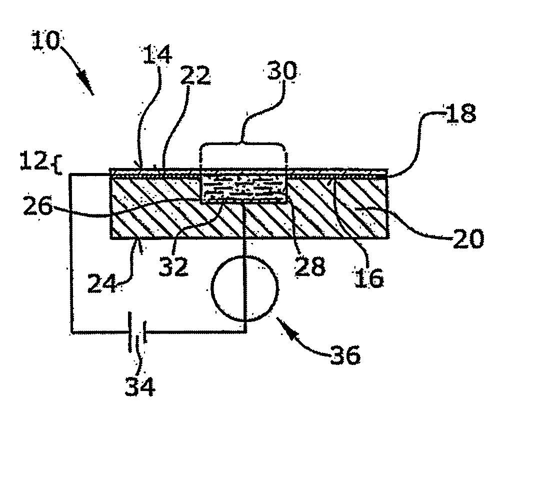
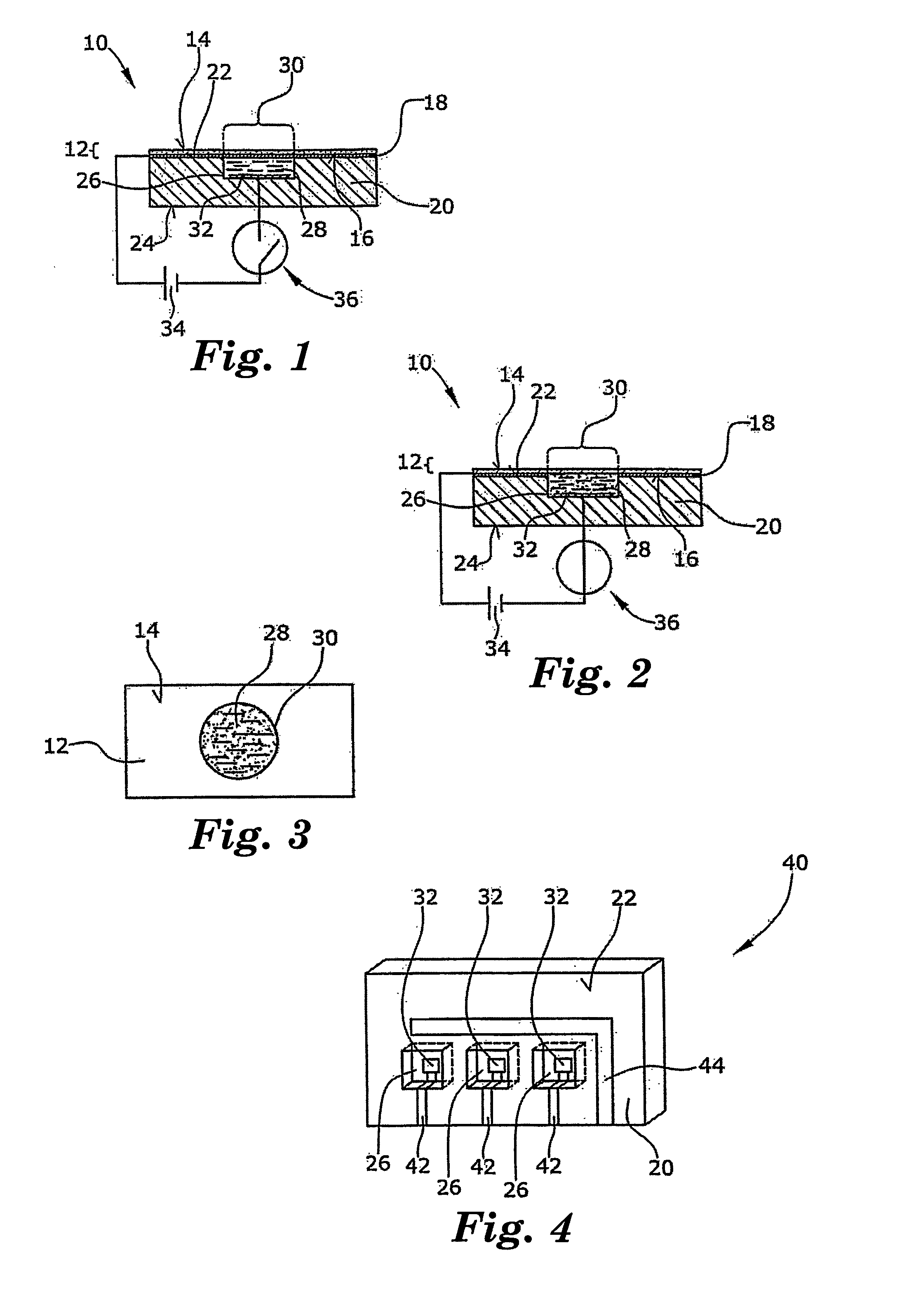
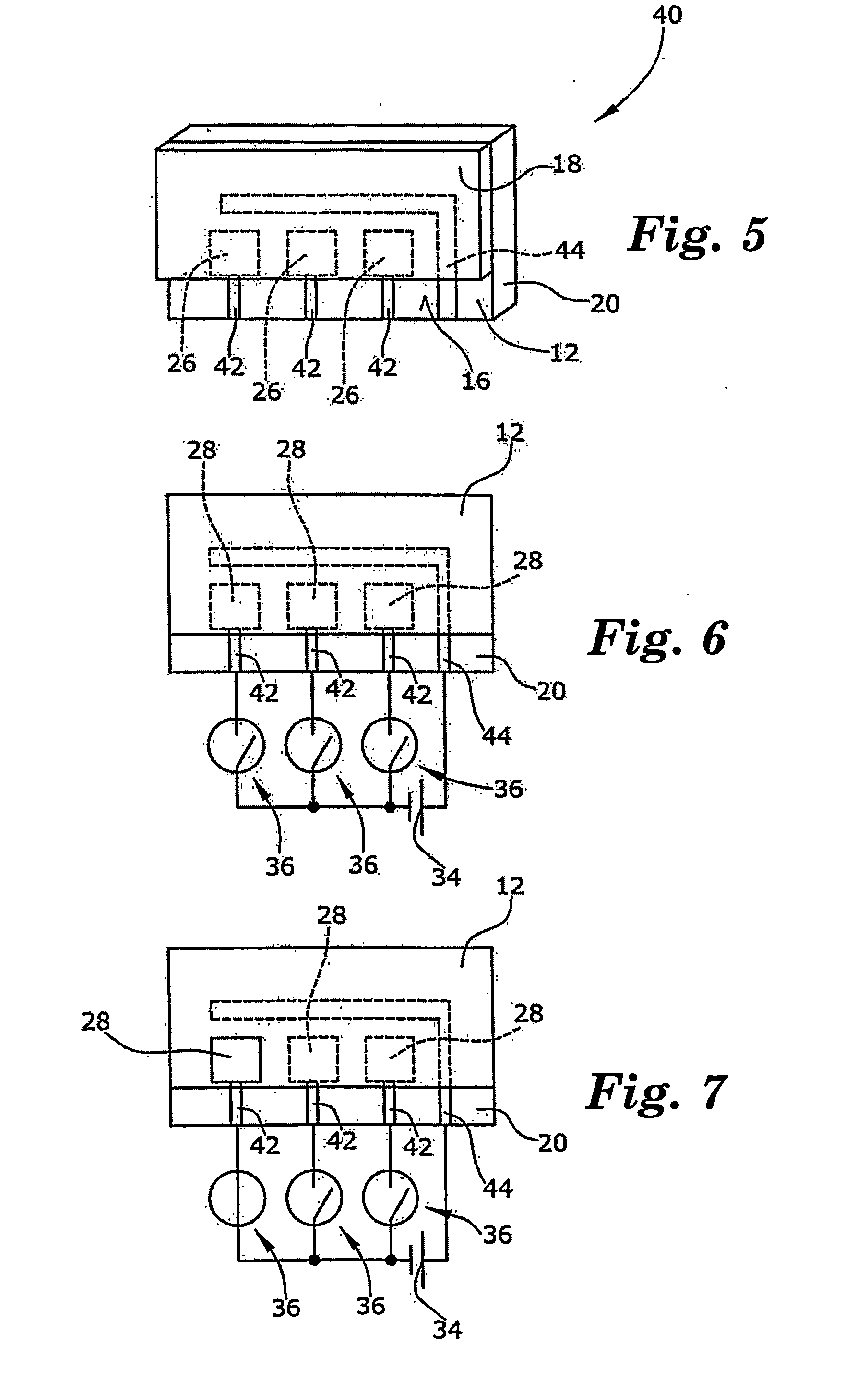
[0046] In the Figures different electrochemical display devices according to the invention are shown wherein like parts of the individual embodiments are referred to by the same reference numerals.

[0047] The basic construction and function of an electrochemical display device according to the invention will be described referring to a first embodiment as shown in FIGS. 1 to 3.

[0048] In FIG. 1 a cross-sectional view of an electrochemical display device 10 is shown. The device 10 comprises a light-transmissive first substrate 12 comprising a glass plate. The first substrate 12 has two major surfaces 14,16 wherein the surface 16 is provided with a metal layer 18 which may, for example, be formed by vapour deposition. The metal layer 18 comprises Cr or Cu and has a thickness of preferably 10 to 50 nm. Other layer thicknesses for example more than 100 nm are also possible. The metal layer 18 reduces the light-transmissivity of the first substrate 12 to a degree depending on the thickne...


PUM


Abstract

An electrochemical display device capable of irreversibly switching from a first indicating state to a second indicating state comprises a substrate (12) having an electrically insulating surface (16), and a first electrode (30) located on at least a part of said surface (16) of said substrate (12), wherein said substrate (12), at least within said part of its surface (16) is light-transmissive, the transmissivity of the combination of said substrate (12) and said first electrode (30) being less than that of said part of said substrate (12). Furthermore, the electrochemical display device comprises a second electrode (32), and an electrolytic liquid (28) arranged between and in electrical contact with said first and second electrodes (30,32), wherein, upon application of an electrical voltage to said first and second electrodes (30,32), material of said first electrode (30) dissolves into said electrolytic liquid (28) exposing at least partially said substrate (12) thereby switching from the first indicating state to the second indicating state.

Description

BACKGROUND OF THE INVENTION [0001] 1. Field of the Invention [0002] The present invention relates to an electrochemical display device capable of irreversibly switching from a first indicating state to a second indicating state and, in particular, to a non-reversible bistable electrochemical display device having a flat design which works reliably and needs comparatively little energy for switching from the first indicating state to the second indicating state. [0003] 2. Related Prior Art [0004] Several indicating or displaying devices of different types and technologies are known in the prior art. Among these types of indicating or displaying devices there are electrochrome display devices (see e.g. DE-A-25 45 391 and DE-A-198 25 371), electroluminescent display devices (see e.g. DE-A-100 42 500), and the widely spread LCD display devices. Moreover, indicating devices are known in which the change of an indicating state results from a chemically induced change of colour (see e.g. E...

Claims


Application Information

Patent Timeline
IPC IPC(8): G02B26/00G02F1/17G04F13/04
CPCG02F1/15G04F13/04G02F1/17
Inventor SCHUMACHER, KNUTKUEPPER, ANTON
Owner 3M INNOVATIVE PROPERTIES CO
Why Eureka
Eureka Blog
Learn More