Optical diffuser with IR and/or UV blocking coating

a technology of optical diffuser and coating, which is applied in the direction of instruments, lighting and heating apparatus, natural mineral layered products, etc., can solve the problems of insufficient heat resistance of certain organic coatings, damage to one or more of the aforesaid optical devices, and infrared (ir) and/or ultraviolet (uv) radiation damage to one or more of the aforesaid devices in which the diffuser is used, so as to reduce the amount of ir

Inactive Publication Date: 2007-03-22
GUARDIAN GLASS LLC
View PDF46 Cites 40 Cited by
  • Summary
  • Abstract
  • Description
  • Claims
  • Application Information

AI Technical Summary

Benefits of technology

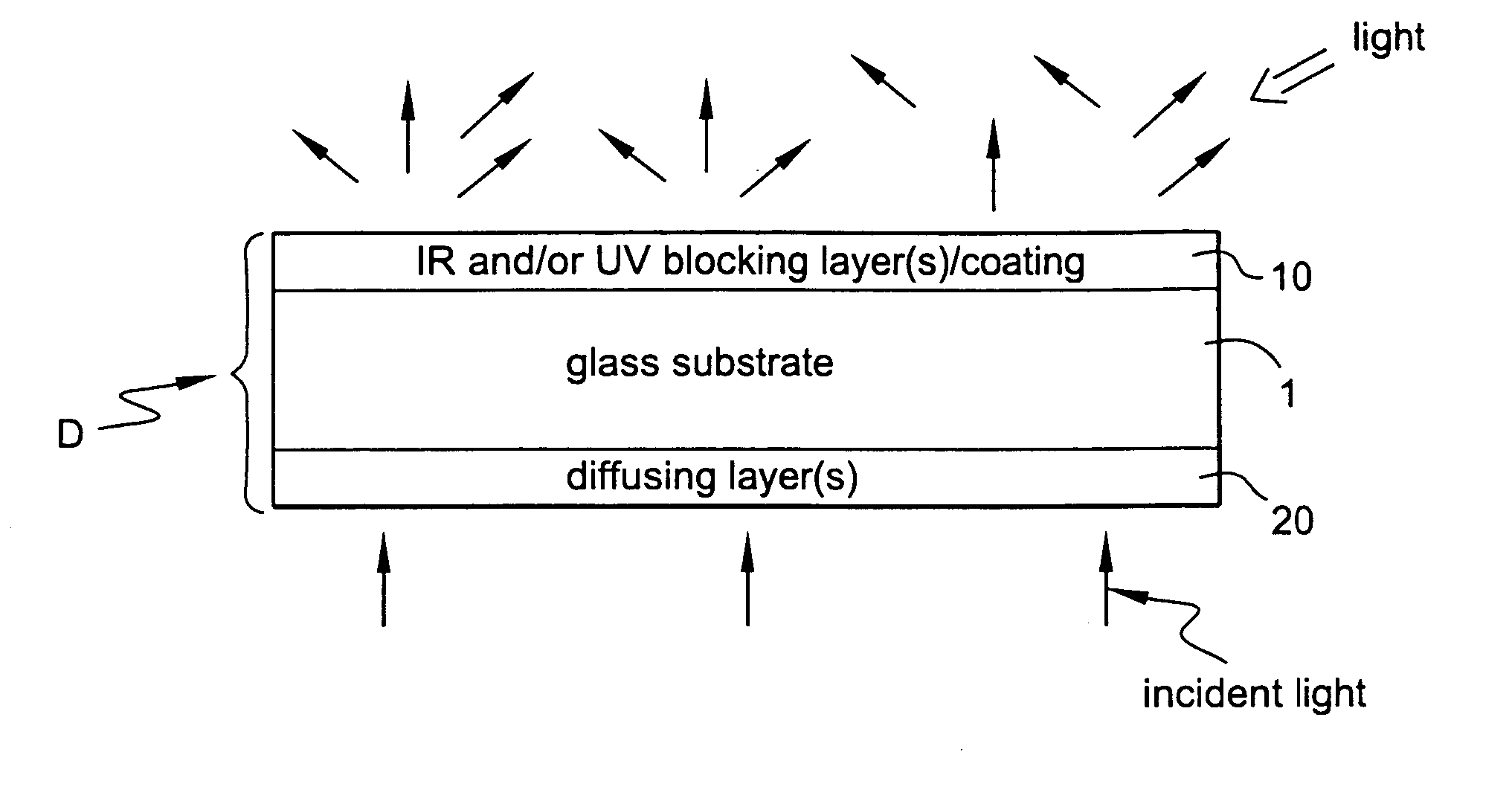
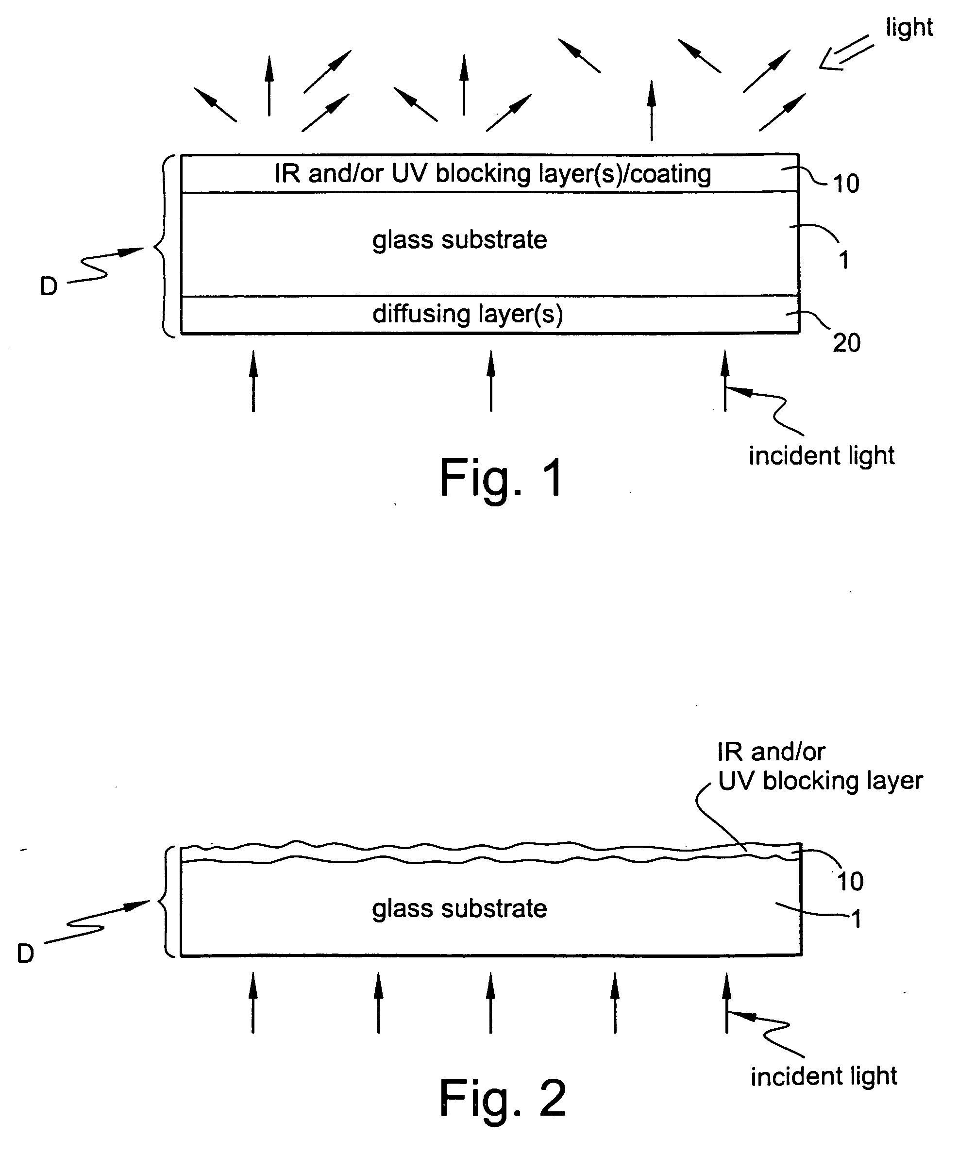
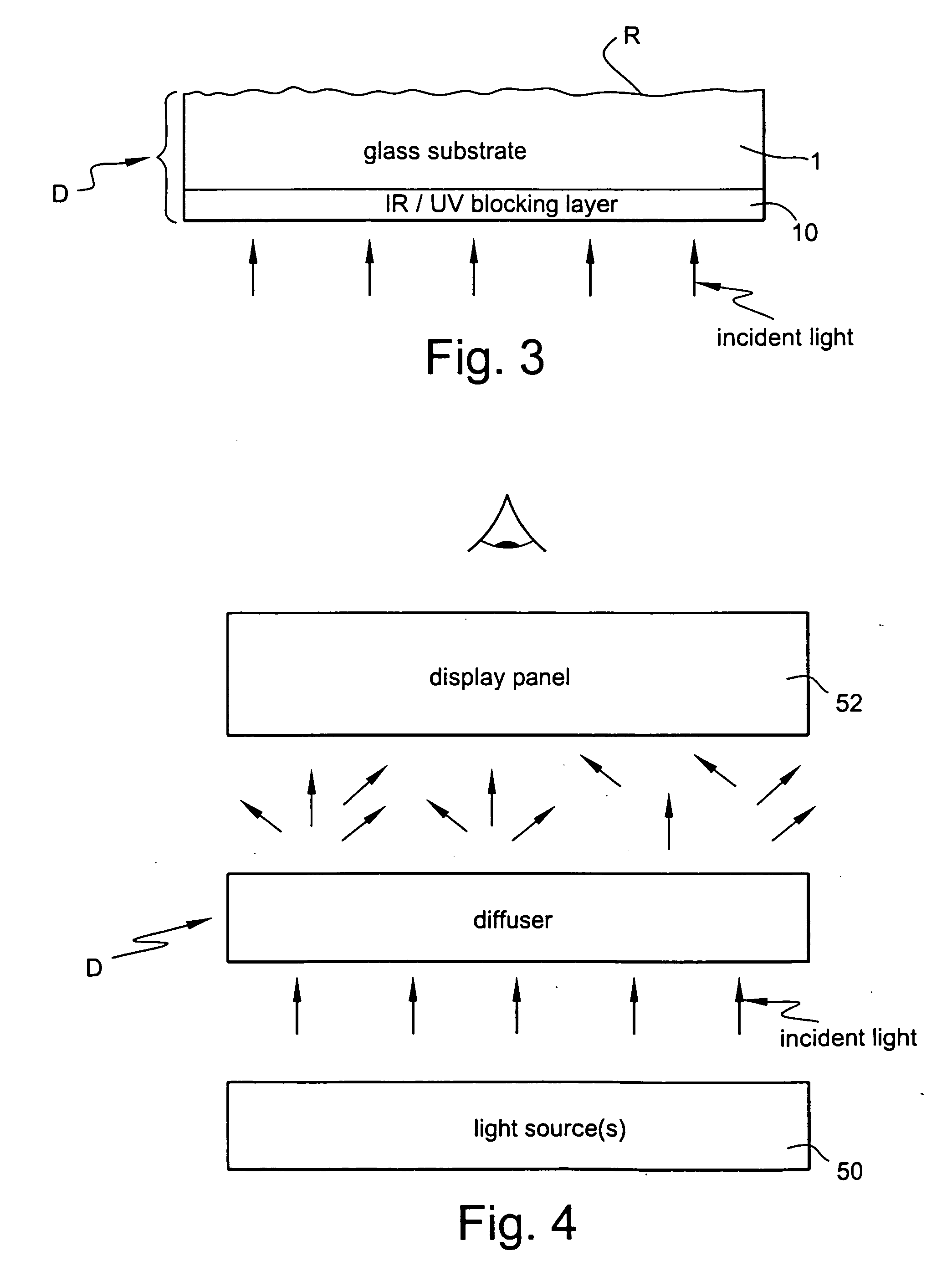
[0007] A diffuser is provided in an illumination system, where the diffuser is capable of blocking significant amounts of IR and/or UV radiation. In certain example embodiments of this invention, the diffuser includes a glass substrate which supports a IR/UV

Problems solved by technology

Infrared (IR) and/or ultraviolet (UV) radiation can damage one or more of the aforesaid devices in which diffusers may be used.
However, unfortunately, conventional diffusers do not block sufficient infrared (IR) and/or ultraviolet (UV) radiation which can lead to damage in one or more of the aforesaid optical devices.
Additionally, it has been found that certain organic coatings are not heat resistant, and cannot withstand the high temperatures associated with thermal tempering

Method used


Image

  • Optical diffuser with IR and/or UV blocking coating
  • Optical diffuser with IR and/or UV blocking coating
  • Optical diffuser with IR and/or UV blocking coating

Examples


examples 1-13

[0061] Examples 1-13 are for purposes of example only and without limitation. In each of Examples 1-13, a UV blocking coating 10 was formed on a flat glass substrate. FIG. 6 illustrates the make-up of the coatings 10 of Examples 1-13. In FIG. 6, “Frit 99” refers to Ferro 20-8099 glass frit, and the “thickness” refers to the thickness of the coating 10.

[0062] Example 1 relates to a diffuser as shown in FIG. 5. The diffuser D of Example 1 was made as follows. A composite slurry was made by mixing 99%, by weight, of Ferro 20-8099 frit (glass frit) with 1%, by weight, of a colloidal dispersion of 10-20 nm particle size cerium oxide (CeO2) particles (Nyacol nano ceria) obtained from Nyacol. Nyacol supplied the dispersion of cerium oxide particles in water (i.e., the colloidal dispersion). The cerium oxide acts as a UV blocker. The UV blocking coating was applied on a 3 mm thick glass substrate 1 by using a screen printing technique using screen with a mesh size 140. The coated glass sub...

examples 14-31

[0077] Examples 14-31 are for purposes of example only and without limitation. Each of the diffusers of Examples 14-31 functions to block significant amounts of IR radiation, and some of these Examples (e.g., Examples 22-25 and 28-31) also block significant amounts of UV radiation. In each of Examples 14-31, an IR and / or UV blocking coating 10 was formed on a flat glass substrate as shown in FIG. 5. FIGS. 23-25 illustrate the make-up of the coatings 10 of Examples 14-31. In FIGS. 23-25, the“thickness” refers to the thickness of the coating 10, b* is a color value, and mesh size refers to the mesh size of the screen used in applying the coating to the glass substrate 1.

[0078] Example 14 relates to a diffuser as shown in FIG. 5. The diffuser D of Example 14 was made as follows. A composite slurry was made by mixing 95%, by weight, of Ferro 20-8099 frit (glass frit) with 5%, by weight, of a colloidal dispersion of 10-20 nm particle size zinc antimonate obtained from Nissan Chemicals. ...


PUM

PropertyMeasurementUnit
Fractionaaaaaaaaaa
Fractionaaaaaaaaaa
Fractionaaaaaaaaaa

Abstract

A diffuser is provided in an illumination system, where the diffuser is capable of blocking significant amounts of infrared (IR) and/or ultraviolet (UV) radiation. In certain example embodiments of this invention, the diffuser includes a glass substrate which supports an IR/UV coating(s) that blocks significant amounts of IR and/or UV radiation thereby reducing the amount of IR and/or UV radiation which can makes its way through the diffuser. In certain example embodiments, the coating may include particulate in a frit matrix so that the coating may both diffuse visible light and perform IR and/or UV blocking.

Description

[0001] This application is a continuation-in-part (CIP) of each of: U.S. Ser. No. 11 / 229,837, filed Sep. 20, 2005 (attorney docket number 3691-891), U.S. Ser. No. 11 / 314,735, filed Dec. 22, 2005 (attorney docket number 3691-978), entitled Optical Diffuser with UV Blocking Coating; U.S. Ser. No. ______, filed Jan. 4, 2006 (attorney docket number 3691-981), and U.S. Ser. No. ______, filed Jan. 4, 2006 (attorney docket number 3691-982), the entire disclosures of which are all hereby incorporated herein by reference.[0002] This invention relates to a diffuser for use in optical devices. In certain example embodiments, the diffuser includes both diffusing functionality and a coating for blocking substantial amounts of infrared (IR) and / or ultraviolet (UV) radiation. One or more IR blocking pigments (e.g., zinc antimonite, fluorinated tin oxide, or an IR coating including at least one IR reflecting layer of a material such as silver) may be provided in the coating in certain example embod...

Claims


Application Information

Patent Timeline
IPC IPC(8): F21V5/00
CPCG02B5/0221G02B5/021G02B5/0278G02B5/0294G02B5/0891G02B5/208G02B5/22C03C8/14C03C17/04C03C17/3411C03C17/3417C03C2217/452C03C2217/475C03C2217/74C03C2218/365G02B1/10G02B5/0242G02F1/133606G02F2201/083G02F2201/086
Inventor SHARMA, PRAMOD K.VARAPRASAD, DESARAJU V.TAYLOR, THOMAS J.
Owner GUARDIAN GLASS LLC
Why Eureka
Try Eureka