Control device for a three-phase machine and method for operating the control device

Inactive Publication Date: 2007-03-22
CONTINENTAL AUTOMOTIVE GMBH
View PDF4 Cites 0 Cited by
  • Summary
  • Abstract
  • Description
  • Claims
  • Application Information

AI Technical Summary

Benefits of technology

[0003] It is accordingly an object of the invention to provide a control device for a three-phase machine and a method for operating the control device that overcome the above-mentioned disadvantages of the prior art devices and methods of this general type, which allows reliable operation of the three-phase machine and is cost-effective. The object of the invention is further to provide a method for operating the control device for the three-phase machine that allows reliable operation of the internal combustion engine and is cost-effective.
[0004] With regard to a first aspect, the invention is characterized by a control device for a three-phase machine containing an inverter, which is connectable on the input side to a direct voltage source and on the output side to the three-phase machine. The control device further has a reactive power converter, which on the output side is terminated by a capacitor and on the input side is connected electrically parallel to the inverter, namely on the input side of the inverter. The reactive power converter, when suitably activated, may convert an alternating component of the input-side current of the inverter so that substantially only a direct current flows on the input side of the inverter. The alternating component of the input-side current of the inverter is an alternating component, which in the absence of the reactive power converter is present during operation of the control device. By use of the reactive power converter it is therefore easily possible to achieve the effect of dramatically reducing or entirely dispensing with the outlay for a voltage link with a capacitance that would be needed without a reactive power converter. This leads to a substantial cost saving because suitable capacitors push up the cost of the control device considerably.
[0006] According to an advantageous development of the first aspect of the invention, there is associated with the control device at last one sensor, the measuring signal of which contributes towards determining the alternating component of the input-side current of the inverter without the presence of the reactive power converter. In this way, particularly precise activation of the reactive power converter for precise compensation of the alternating component is easily possible.
[0008] According to a further advantageous development of the first aspect of the invention, the reactive power converter is a step-up converter. This has the advantage that across the output-side capacitor of the reactive power converter a higher voltage step is usable than across an optionally provided capacitor in the voltage link. This has the result that the capacitances of the capacitors may be set lower, thereby reducing the total outlay for the control device.
[0009] In this connection, it is particularly advantageous when the step-up converter is a polyphase step-up converter. This has the advantage that the individual phases of the step-up converter are activated with staggered timing and so, on the whole, a very high dynamic response of the step-up converter is possible, this allowing particularly precise compensation of the alternating component of the input-side current of the inverter. What is more, the currents may be apportioned to the individual branches of the step-up converter.
[0010] According to a further advantageous development of the first aspect of the invention, the reactive power converter is an inverting DC / DC converter. This has the advantage that the voltage, which drops above the capacitor, during operation may even become zero and so the voltage step across the capacitor may be set very high. In this connection, it is further advantageous when the inverting DC / DC converter is configured as a polyphase inverting DC / DC converter. The advantages in this regard correspond to the polyphase step-up converter.

Problems solved by technology

This leads to a substantial cost saving because suitable capacitors push up the cost of the control device considerably.

Method used


Image

  • Control device for a three-phase machine and method for operating the control device
  • Control device for a three-phase machine and method for operating the control device
  • Control device for a three-phase machine and method for operating the control device

Examples


Embodiment Construction

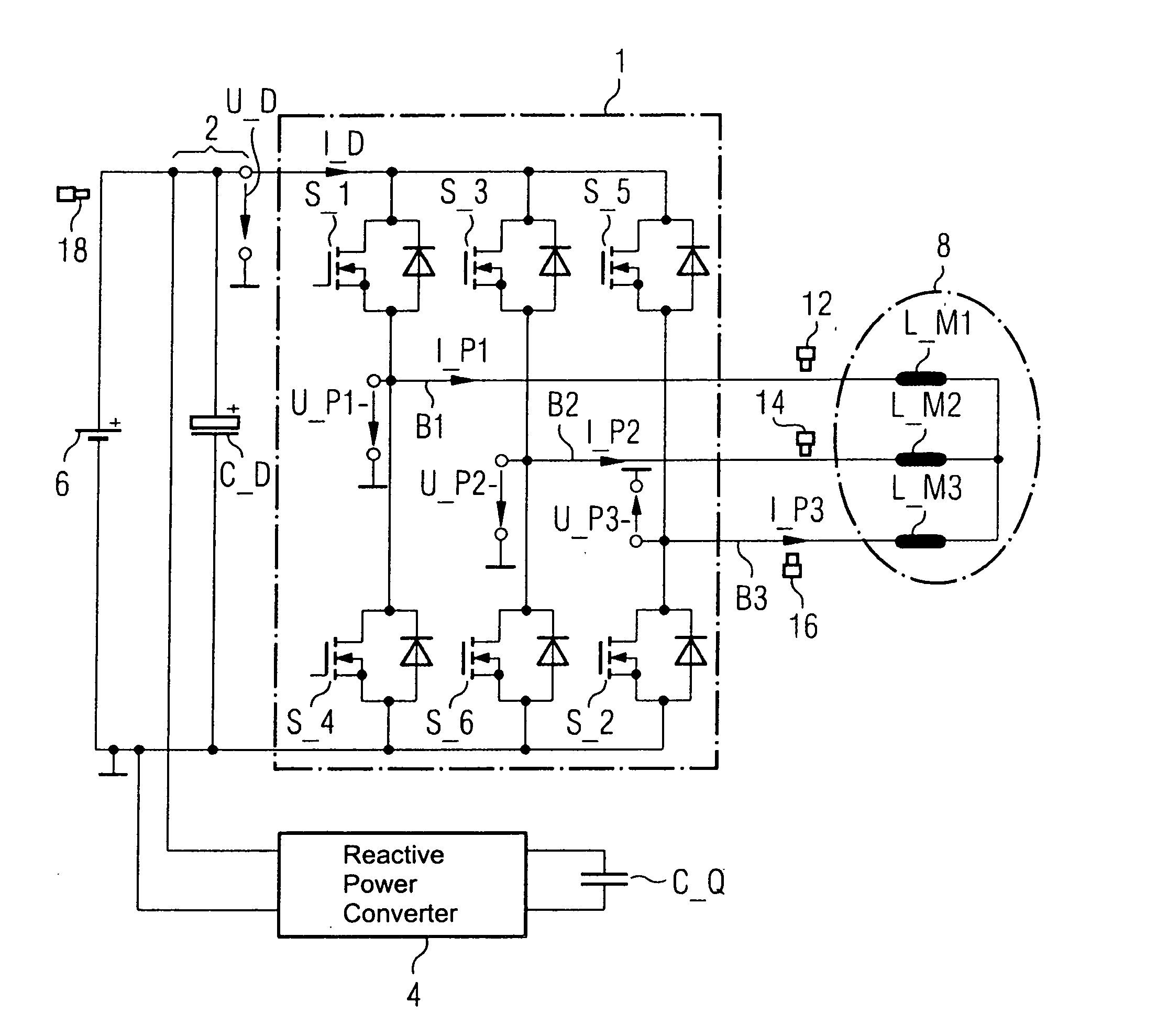
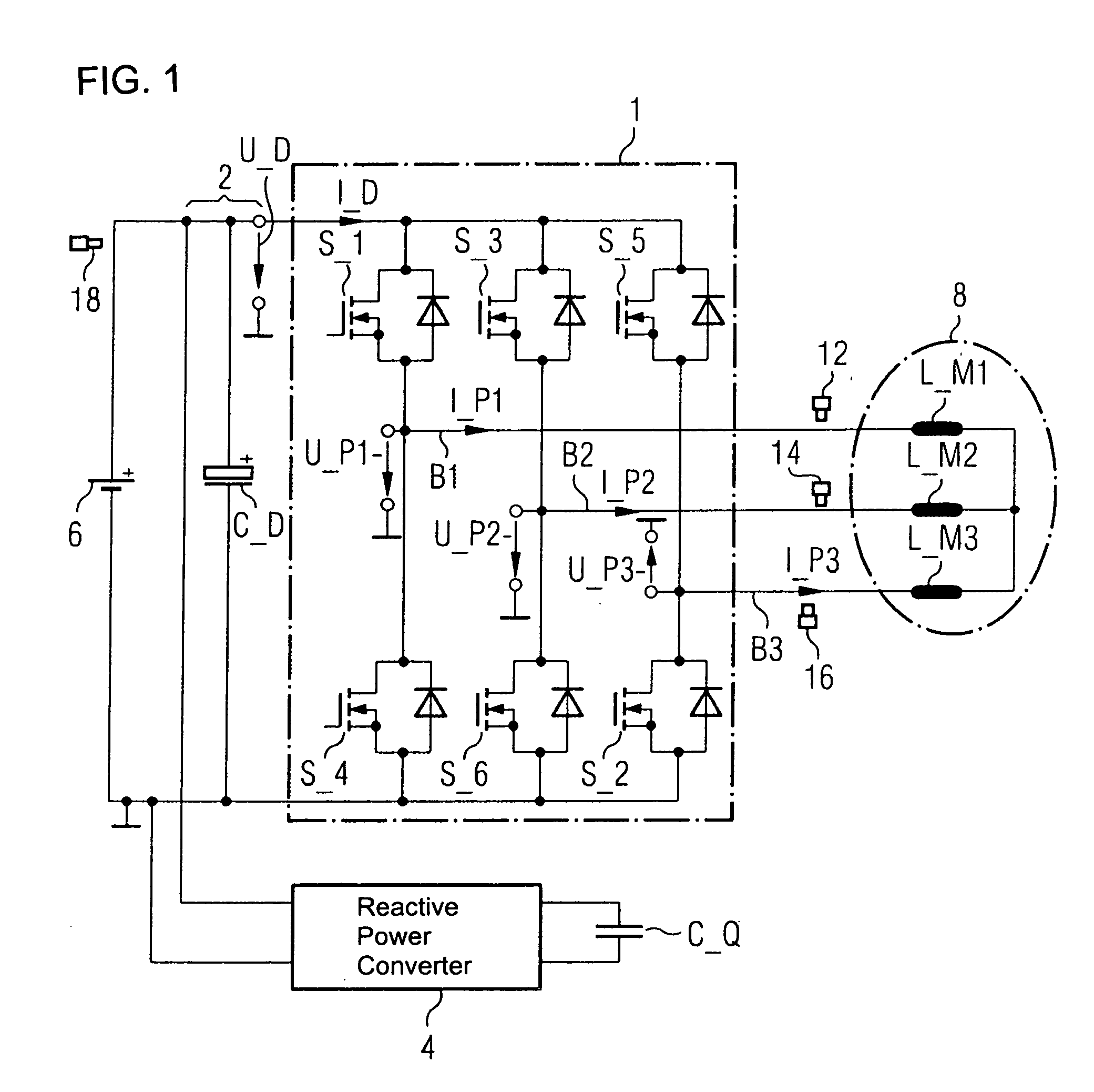
[0022] In all the figures of the drawing, sub-features and integral parts that correspond to one another bear the same reference symbol in each case. Referring now to the figures of the drawing in detail and first, particularly, to FIG. 1 thereof, there is shown a control device associated with a three-phase machine 8. The three-phase machine may be for example an asynchronous machine or a synchronous machine. The control device contains an inverter 1, a voltage link 2 and a reactive power converter 4. On an input side, for the operation of the control device, the inverter 1 is connected electrically to a direct voltage source 6, which may be for example a battery of a motor vehicle. The three-phase machine is preferably used in a motor vehicle. It may however also be used for any desired other application.

[0023] The inverter 1 includes first to third bridge branches B1 to B3 having switches S1, S3, S5 and S4, S6, S2 disposed at a high side and a low side respectively. Via the brid...


PUM


Abstract

A control device for a three-phase machine contains an inverter, which can be connected on the input side to a direct voltage source and on the output side to the three-phase machine. The control device further has a reactive power converter, which on the output side is terminated by a capacitor and on the input side is disposed electrically parallel to the inverter, namely on the input side of the inverter.

Description

CROSS-REFERENCE TO THE RELATED APPLICATION [0001] This application claims the priority, under 35 U.S.C. §119, of German application DE 10 2005 045 122.5, filed Sep. 21, 2005; the prior application is herewith incorporated by reference in its entirety. BACKGROUND OF THE INVENTION Field of the Invention [0002] The invention relates to a control device for a three-phase machine and a method for operating the control device. Three-phase machines are used in particular to supply a vehicle electrical system in a generator mode of a motor vehicle and / or in an engine mode. Here, the so-called hybrid drive is increasingly gaining importance. In this case, besides an internal combustion engine the vehicle also has the three-phase machine for driving the vehicle. Components disposed in a motor vehicle have to be able to withstand extreme variations in temperature and have a long service life. SUMMARY OF THE INVENTION [0003] It is accordingly an object of the invention to provide a control devi...

Claims


Application Information

Patent Timeline
IPC IPC(8): H02M7/537
CPCH02J3/1835Y02E40/30H02P27/06
Inventor RENKEN, FOLKER
Owner CONTINENTAL AUTOMOTIVE GMBH
Why Eureka
Try Eureka