Body lumen shaping device with cardiac leads

a technology of body lumen and shaping device, which is applied in the field of body lumen shaping device with cardiac leads, can solve the problems of increased workload on the heart of patients, serious health risks, and increased blood pressure, and achieve the effect of reducing the regurgitation of the mitral valv

Inactive Publication Date: 2007-03-22
CARDIAC DIMENSIONS
View PDF99 Cites 103 Cited by
  • Summary
  • Abstract
  • Description
  • Claims
  • Application Information

AI Technical Summary

Problems solved by technology

The added workload on a patient's heart, and the increased blood pressure in the lungs caused by this heart condition, poses serious health risks if this condition is left untreated.
Failure of the mitral valve leaflets to open and close properly can be caused by damage to the leaflets.
For example, rheumatic fever and other infections can damage valve leaflets and cause scarring.
In addition, if one or more of the cordlike structures attaching the leaflets to the heart muscles break, the valve may also leak.
However, an attendant drawback of surgical valve replacement, or repair, is the high morbidity, cost and trauma associated with these treatments.
However, accessing and implanting leads of EP devices to the coronary sinus can be difficult, as these devices are not particularly designed for good pushability.
Also, these leads can be difficult to maintain in position within the coronary sinus as movement of the heart during heartbeats tends to cause dislodgement of these components.

Method used


Image

  • Body lumen shaping device with cardiac leads
  • Body lumen shaping device with cardiac leads
  • Body lumen shaping device with cardiac leads

Examples


Embodiment Construction

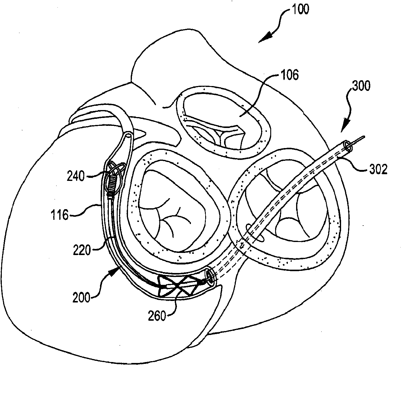
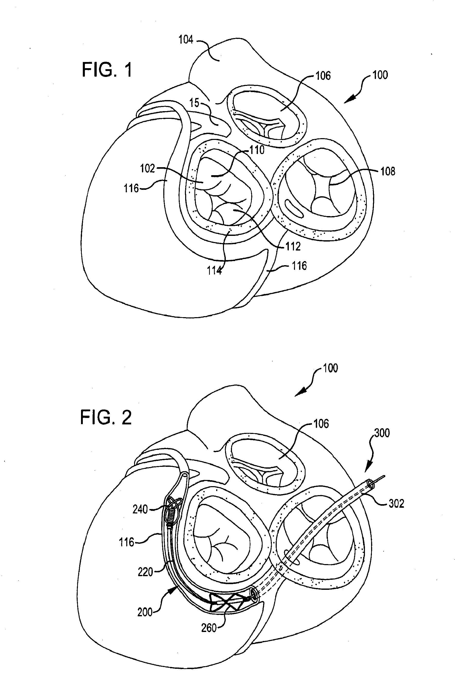
[0026]FIG. 1, is a superior view of a heart 100 with the atria removed. It is provided to aid in the understanding of the present invention. As pictured, the heart comprises several valves including mitral valve 102, pulmonary valve 104, aortic valve 106 and tricuspid valve 108.

[0027] Turning to mitral valve 102, this valve includes anterior cusp 110, posterior cusp 112 and annulus 114. Annulus 114 encircles cusps 110 and 112 and functions to maintain their respective spacing to ensure complete mitral valve closure during left ventricular contractions of the heart 100. As illustrated, coronary sinus 116 partially encircles mitral valve 102 and is adjacent to mitral valve annulus 114. Coronary sinus 116 is part of the venous system of heart 100 and extends along AV groove between the left atrium and the left ventricle. This places coronary sinus 116 essentially within the same plane as mitral valve annulus 114, making coronary sinus 116 available for placement of shaping device 200 ...


PUM


Abstract

A shaping device and a cardiac lead, both adapted to be disposed in a coronary sinus of a patient's heart, are provided. In one method, a patient is treated by deploying in the patient's coronary sinus a shaping device and a cardiac lead and using the shaping device to modify mitral valve geometry.

Description

CROSS-REFERENCE [0001] This application is a divisional application of U.S. patent application Ser. No. 11 / 132,786, “Body Lumen Shaping Device With Cardiac Leads”, filed on May 18, 2005, which is a continuation-in-part of U.S. patent application Ser. No. 10 / 066,426, “Fixed Length Anchor and Pull Mitral Valve Device and Method”, filed Jan. 30, 2002, now U.S. Pat. No. 6,976,995, which is incorporated herein by reference in its entirety and to which application we claim priority under 35 USC § 120.FIELD OF THE INVENTION [0002] The present invention generally relates to devices and methods for treating a mitral valve and delivering and / or maintaining one or more electrophysiology (EP) devices, such as a cardiac lead, in a coronary sinus. BACKGROUND OF THE INVENTION [0003] The mitral valve is located in the left side of the heart, between the left upper chamber (atrium) and left lower chamber (ventricle). The valve comprises two flaps, called leaflets, which normally close each time the ...

Claims


Application Information

Patent Timeline
Patent Type & Authority Applications(United States)
IPC IPC(8): A61B5/042A61F2/24A61N1/05A61B17/00
CPCA61B2017/00243A61N2001/0585A61N1/057A61F2/2451
Inventor MATHIS, MARK L.NIEMINEN, GREGORY D.REUTER, DAVID G.
Owner CARDIAC DIMENSIONS
Why Eureka
Try Eureka