Method for operation of an internal combustion engine

a technology of internal combustion engine and process, which is applied in the direction of machines/engines, output power, electric control, etc., can solve the problems that the change in the charge desired by the driver or the inability to present a regulation system immediately, and achieve the effect of improving the non-steady-state response behavior

Active Publication Date: 2007-03-29
BAYERISCHE MOTOREN WERKE AG
View PDF1 Cites 4 Cited by
  • Summary
  • Abstract
  • Description
  • Claims
  • Application Information

AI Technical Summary

Benefits of technology

[0009] The invention is based on the concept of charge control according to the above-described Miller process (early / late intake closure in connection with the operation of a charger). It is intended to specify a process by means of which one improves the non-steady-state response behavior of a supercharged internal combustion engine with a variable valve drive mechanism at least on the intake side. In particular, shorter times for meeting charge requirements which occur is intended to be ensured.
[0010] According to the invention this objective is realized as follows. Due to the fact that in an internal combustion engine during the operation of the charger a reserve (control time reserve or stroke reserve) available with respect to the intake closure control time and / or the stroke of a variable intake valve drive mechanism which is present is utilized in addition by in each operating cycle of the internal combustion engine an increased charge amount (in particular air mass) being supplied to the combustion space until the predefined theoretical charge is reached, the time required to meet the charge requirement can be reduced significantly and thus the response time of the internal combustion engine can be shortened.

Problems solved by technology

It is problematic that in a supercharged motor with a variable valve drive mechanism it cannot be ensured that the pre-controlled charge also corresponds to the charge actually present in the next cycle since the charge pressure which is required to reach the desired charge cannot be presented in the following operational cycle.
The change in the charge desired by the driver or a regulation system cannot be presented immediately due to the time delay of the build-up of charge pressure (a so-called turbolag).

Method used


Image

  • Method for operation of an internal combustion engine
  • Method for operation of an internal combustion engine
  • Method for operation of an internal combustion engine

Examples


Embodiment Construction

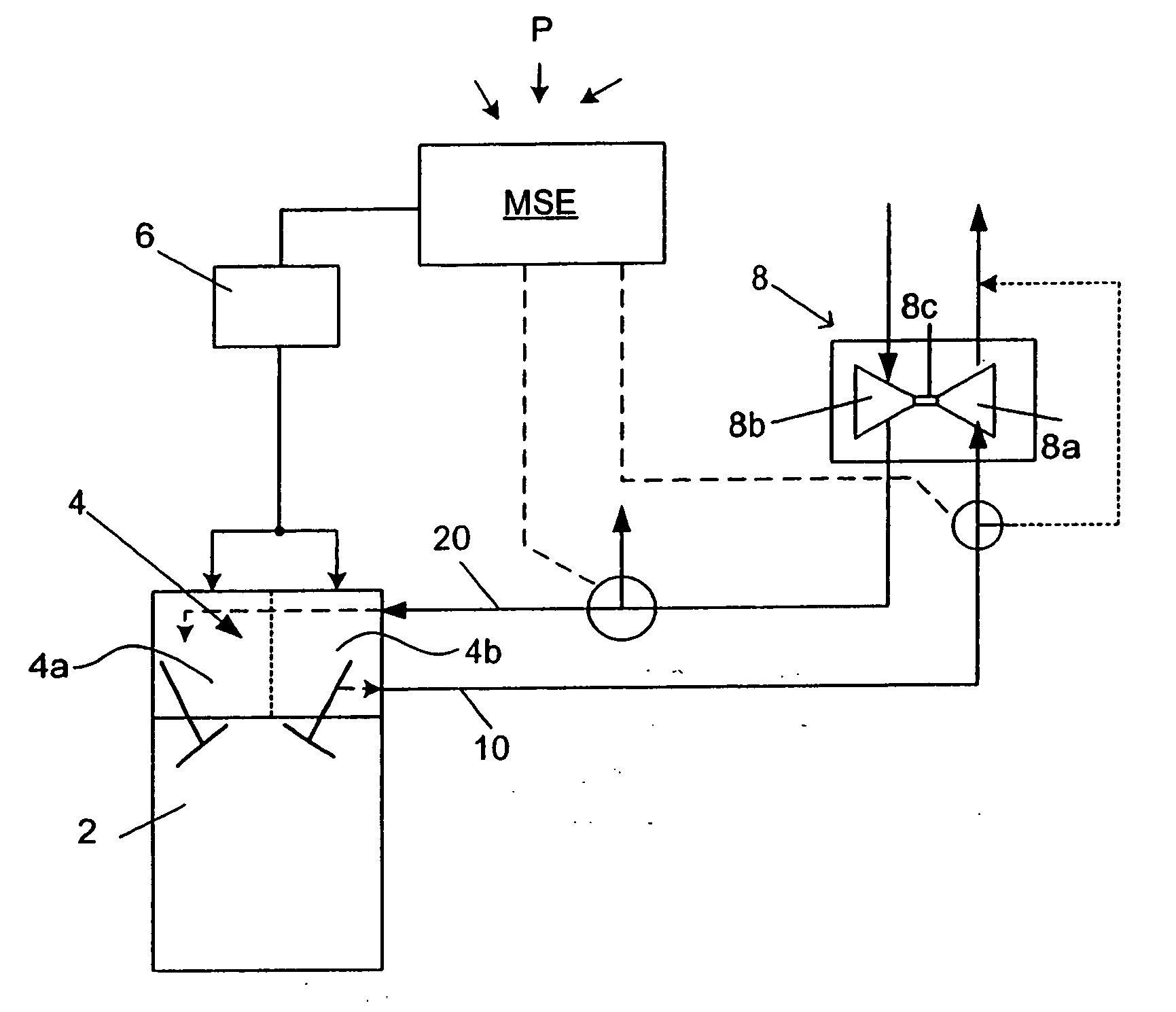
[0021]FIG. 1 shows in a highly schematic representation an internal combustion engine 2 with an electromagnetic fully variable valve drive mechanism 4 (with variable intake valve drive mechanism 4a and variable exhaust valve drive mechanism 4b) and a control device 6 for the targeted driving of the electromagnetic variable valve drive mechanism 4. A fully variable valve drive mechanism of this type can, for example, be designed as an electrical, electromagnetic, or hydraulic mechanism. An essential feature of a drive mechanism of this type is the individual drivability or displaceability of individual valves or groups of valves. The internal combustion engine 2 is connected on the exhaust gas side via an exhaust gas line 10, and on the intake side via an intake line 20, to a charger device 8 (for example, an exhaust gas turbocharger). Through the exhaust gas flow produced by the internal combustion engine 2 the charger device 8 can be driven via its turbine wheel 8a. The turbine whe...


PUM


Abstract

A process for operating an internal combustion engine with a charging device such as a turbocharger and with an intake valve drive mechanism which is variable with respect to its intake valve control times and / or its intake valve stroke. Upon recognition of a positive charge requirement during the operation of the charging device, the at least one variable intake valve drive mechanism is driven in such a manner that an available stroke reserve and / or intake closure control time reserve is utilized to increase the charge amount introduced into an engine cylinder.

Description

[0001] This application is a Continuation of International Patent Application No. PCT / EP2005 / 005516, filed May 20, 2005, and claims the priority of DE 10 2004 026 405.8, filed May 29, 2004, the disclosures of which are expressly incorporated by reference herein.BACKGROUND AND SUMMARY OF THE INVENTION [0002] The invention relates to a process for operating an internal combustion engine, in particular for operating an internal combustion engine for a motor vehicle equipped with a charging device such as a turbocharger. [0003] The charge control in an internal combustion engine with a variable valve drive mechanism is essentially determined by, on the one hand, the intake valve stroke and / or the intake control time during which an intake valve frees the intake opening to the combustion space and thus the available air mass or charge can be supplied to the combustion space (or the charge is sucked in) and, on the other hand, due to the density of the available charge. The density, and t...

Claims


Application Information

Patent Timeline
Patent Type & Authority Applications(United States)
IPC IPC(8): F02D23/00F02B33/44F02B37/00F02D13/02F02D41/00F02D41/10
CPCF02B37/00F02B2275/32F02D13/0226F02D13/0253F02D13/0269Y02T10/142F02D41/0007F02D41/10F02D2041/001F02D2250/22Y02T10/144F02D23/00Y02T10/12
Inventor ROTTENKOLBER, GREGORBALLES, FABIAN
Owner BAYERISCHE MOTOREN WERKE AG
Why Eureka
Try Eureka