Phase self-correcting circuit

A phase and circuit technology, applied in the field of signal transmission, can solve the problems of shielding measures restricting practical application scenarios, poor versatility, and increasing the manufacturing cost of circuit systems.

Active Publication Date: 2020-10-23
SUZHOU LANGCHAO INTELLIGENT TECH CO LTD
View PDF5 Cites 3 Cited by
  • Summary
  • Abstract
  • Description
  • Claims
  • Application Information

AI Technical Summary

Problems solved by technology

[0003] In related technologies, reducing the length of the path, adding electromagnetic shielding components, or grounding the signal to prevent the phase change during signal transmission, limiting the length of the trace, increasing the space for PCB traces, and adding additional shielding measures not only It will limit the practical application scenarios, have poor versatility, and cannot completely eliminate the phase change, and will increase additional manufacturing costs
Another related technology uses an integrated IC chip for clock reconstruction in the terminal, and uses the chip to perform signal reconstruction processing in the terminal to achieve phase correction. The integrated IC chip is expensive and increases the manufacturing cost of the entire circuit system.
[0004] In view of this, how to solve the problems of poor versatility and high manufacturing cost of related technologies is a technical problem to be solved by those skilled in the art

Method used


Image

  • Phase self-correcting circuit
  • Phase self-correcting circuit
  • Phase self-correcting circuit

Examples


Embodiment Construction

[0035] In order to enable those skilled in the art to better understand the solution of the present invention, the present invention will be further described in detail below in conjunction with the accompanying drawings and specific embodiments. Apparently, the described embodiments are only some of the embodiments of the present invention, but not all of them. Based on the embodiments of the present invention, all other embodiments obtained by persons of ordinary skill in the art without making creative efforts belong to the protection scope of the present invention.

[0036] The terms "first", "second", "third" and "fourth" in the specification and claims of this application and the above drawings are used to distinguish different objects, rather than to describe a specific order . Furthermore, the terms "comprising" and "having", and any variations thereof, are intended to cover a non-exclusive inclusion. For example, a process, method, system, product, or device compris...


PUM


Abstract

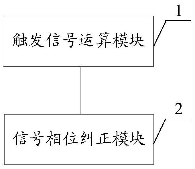
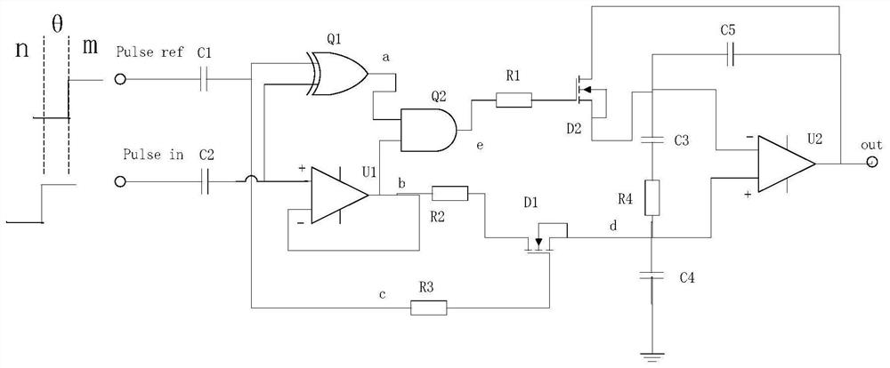
The invention discloses a phase self-correcting circuit. The phase self-correcting circuit comprises a trigger signal operation module and a signal phase correcting module, the trigger signal operation module and the signal phase correction module are both composed of a plurality of discrete components. The trigger signal operation module is used for performing logical operation on the input phasestandard reference signal and the actual transmission signal to obtain a target trigger signal of the trigger signal phase correction module; the signal phase correction module is used for outputtinga self-correction transmission signal with the same waveform as the phase standard reference signal based on the trigger mode of the target trigger signal and the actual transmission signal; the phase self-correction of the actual transmission signal is realized, so that the change of the signal phase caused by various external reasons is automatically corrected, the time sequence requirement ina long-distance transmission scene is met, and the whole circuit is simple in structure, high in universality and low in manufacturing cost.

Description

technical field [0001] The present application relates to the technical field of signal transmission, in particular to a phase self-correcting circuit. Background technique [0002] As we all know, the change of the signal phase usually reflects a physical change caused by the external interference of the signal in the transmission line. For example, as various external factors such as electromagnetic interference cause interference, the phase of the signal will change accordingly. Leading, there may also be a lag, and the change of the phase usually leads to timing confusion, which is not conducive to the stable transmission of signals. It can be seen that it is very necessary to correct the changed phase or prevent the phase change to ensure stable signal transmission. [0003] In related technologies, reducing the length of the path, adding electromagnetic shielding components, or grounding the signal to prevent the phase change during signal transmission, limiting the l...

Claims


Application Information

Patent Timeline
Patent Type & Authority Applications(China)
IPC IPC(8): H03K19/003H03L7/00
CPCH03K19/00323H03L7/00H03K2005/00286
Inventor 刘洁王旭
Owner SUZHOU LANGCHAO INTELLIGENT TECH CO LTD
Why Eureka
Try Eureka