Shift lever lock device for vehicular automatic transmission
a technology of automatic transmission and shift lever, which is applied in the direction of mechanical control devices, process and machine control, instruments, etc., can solve the problems of preventing the device from providing a space-saving structure and unable to provide a smooth and quick rotary movement with the follower, so as to reduce the load applied and save the cost of materials
- Summary
- Abstract
- Description
- Claims
- Application Information
AI Technical Summary
Benefits of technology
Problems solved by technology
Method used
Image
Examples
first embodiment
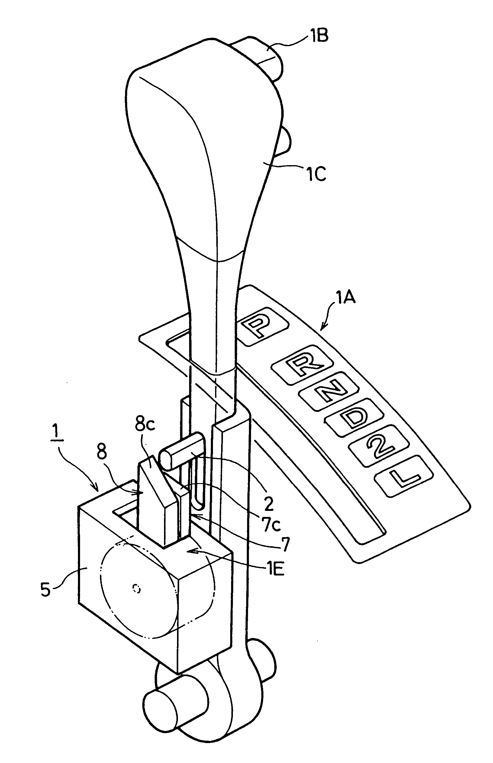
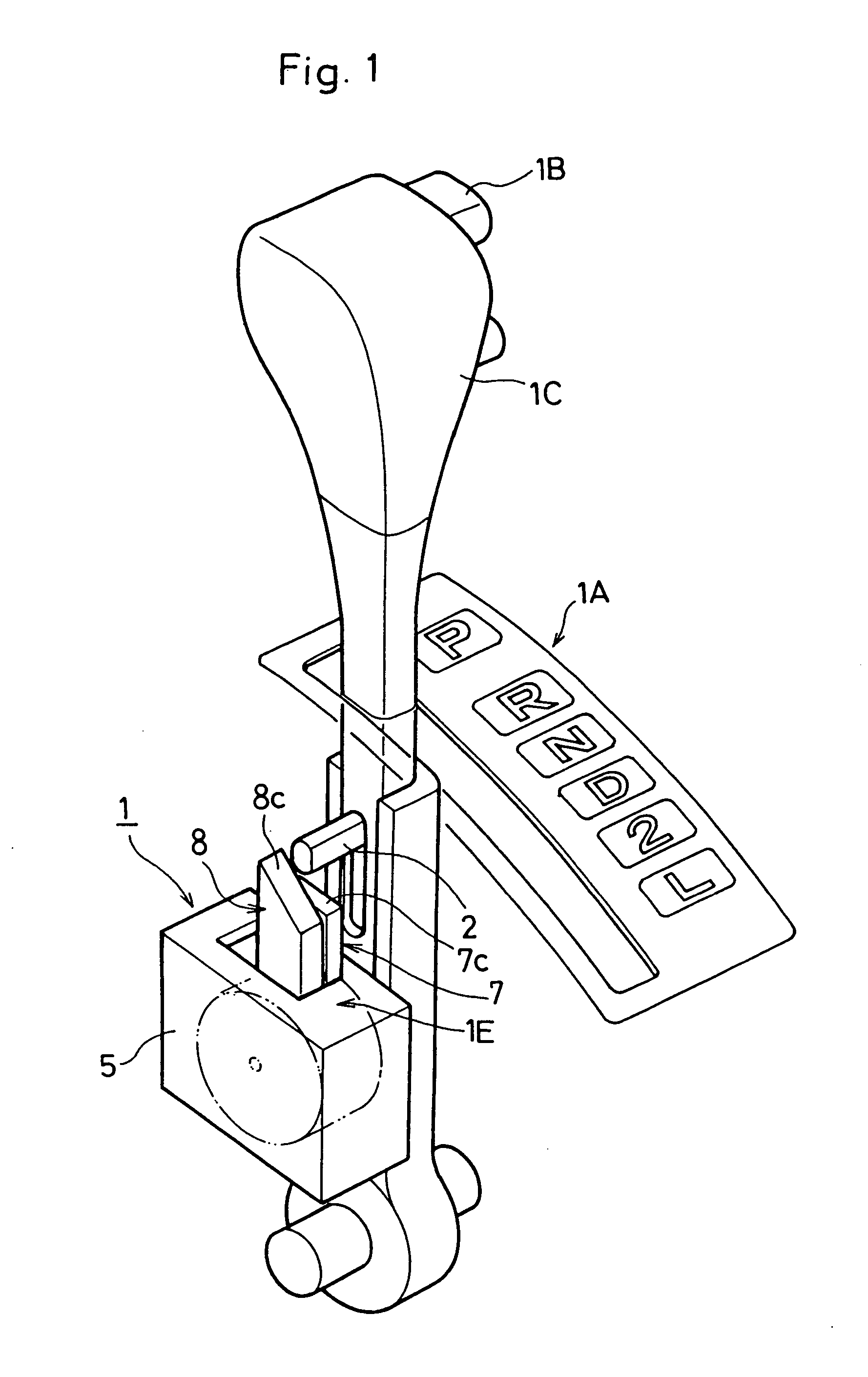
[0043] Referring to FIGS. 1 and 6 which show a shift lever lock device 1 for vehicular automatic transmission according to the invention, an operational shift portion 1A is provided in the vehicular automatic transmission as shown in FIG. 1. In the shift lever lock device 1, a lock mechanism portion 1E is provided within a casing 5. The shift lever lock device 1 may be of any type regardless of whether it is of straight-gate type or column-gate type one.
[0044] The operational shift portion 1A has a shift lever 1C, an upper end of which has a select button 1B to be operated toward P-range position (parking position), R-range position, N-range position, D-range position, 2-position and L-range position.
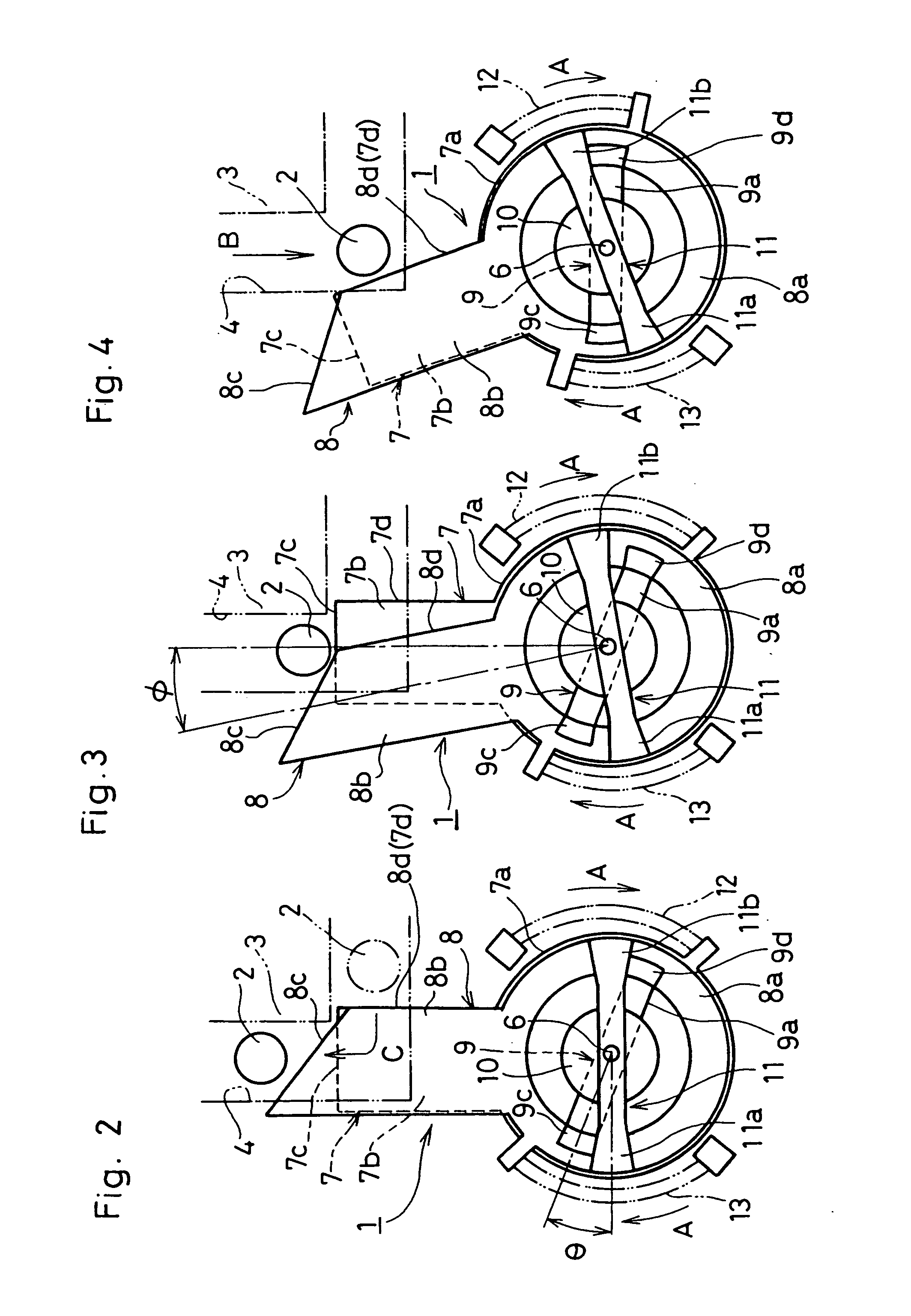
[0045] As shown in FIG. 2, the shift lever 1C is in the P-range position, and a decent pin 2 is adapted to slide along a detent groove 4 provided on a detent plate 3 which is omitted in FIG. 1. The detent pin 2 axially moves along the shaft lever 1C in association with the select butto...
second embodiment
[0071]FIG. 7 shows the invention in which the first movable core 11 omits a part of the support portion. 9a with the second movable core 11 substantially halved in length. This contributes to saving the materials to realize the lightweight movable cores 9, 11.
third embodiment
[0072]FIGS. 8 through 15 show the invention in which the lock plate 7 and the link plate 8 locate their lower cylindrical portions 7a, 8a in a casing 15 (refer to FIGS. 8, 9) with the upper leg portions 7b, 8b exposed outside the casing 15 as shown in FIG. 10.
[0073] In more tangible terms, the lock plate 7 fits the lower cylindrical portion 7a to rotatably slide into an annular inner wall 15a defined on a left half of the casing 15. The link plate 8 fits the lower cylindrical portion 8a to rotatably slide into an annular inner wall 15b defined on a right half of the casing 15.
[0074] Between the casing 15 and the lock plate 7, a first torsional spring 17 is provided as a first urging member. Between the casing 15 and the link plate 8, a second torsional spring 18 is provided as a second urging member. The annular inner wall 15b is designed to be diametrically larger than the annular inner wall 15a so as to define a stepped border portion 16 therebetween. The stepped border portion 1...
PUM
 Abstract
Description
Claims
Application Information
 - R&D
- Intellectual Property
- Life Sciences
- Materials
- Tech Scout
- Unparalleled Data Quality
- Higher Quality Content
- 60% Fewer Hallucinations
Browse by: Latest US Patents, China's latest patents, Technical Efficacy Thesaurus, Application Domain, Technology Topic, Popular Technical Reports.
© 2025 PatSnap. All rights reserved.Legal|Privacy policy|Modern Slavery Act Transparency Statement|Sitemap|About US| Contact US: help@patsnap.com


