Charging apparatus and charging system

a charging system and charging apparatus technology, applied in the field of charging apparatus and charging system, can solve the problems of not performing verification operation and consuming much power of charging stand, so as to reduce the power consumption of charging stand, avoid power supply, and reduce the effect of charging stand power consumption

Active Publication Date: 2007-03-29
SONY CORP
View PDF7 Cites 331 Cited by
  • Summary
  • Abstract
  • Description
  • Claims
  • Application Information

AI Technical Summary

Benefits of technology

[0015] In an embodiment according to the invention, an electrical-contact failure does not occur due to contactless charging, and it is possible to detect a correct cellular phone due to authentication with a contactless IC card unit, irrespective of the remaining battery life of the cellular phone, thereby making it possible to avoid supplying power to a foreign object in error.
[0016] Further, since authentication of a contactless IC card unit is performed when a cellular phone is physically put on the charging stand, it is not necessary to always consume power to determine a foreign object before the start of charging, thus making it possible to reduce the power consumption of the charging stand.
[0017] After the start of charging, the contactless IC card reader is controlled into a low-power mode. Alternatively, if a foreign object is put on the charging stand, power is not supplied to the foreign object. Thereby, it is possible to reduce the power consumption of the charging stand.

Problems solved by technology

In the related art, there is a problem that the charging stand consumes much power because a circuit for detecting a foreign object always operates.
Further, since the verification of whether the object put on the charging stand is a foreign object or a correct device is conducted on the basis that a certain amount of electricity remains in a battery of a device to be charged, there is a problem that the above verification operation is not performed if the amount of electricity remaining in the battery is extremely small.

Method used


Image

  • Charging apparatus and charging system
  • Charging apparatus and charging system
  • Charging apparatus and charging system

Examples


Embodiment Construction

[0022] Hereinafter, a preferred embodiment of the present invention will be described in detail with reference to the accompanying drawings.

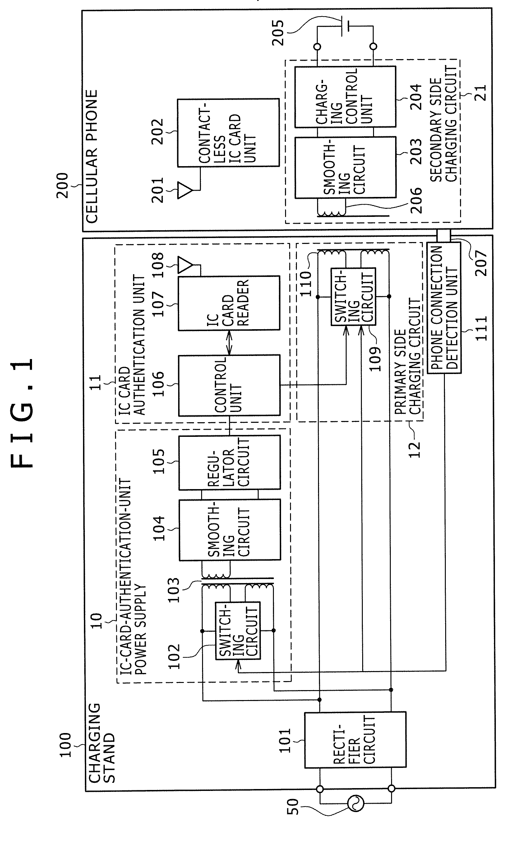
[0023]FIG. 1 is a block diagram showing an example of the configuration of a charging system in an embodiment according to the invention. The charging system represents a cellular phone 200 which is an example of portable electronic devices at the charged side and a charging stand 100 which is a charging apparatus at the charging side.

[0024] The charging stand 100 includes a rectifier circuit 101 which is connected to a commercial power source 50 and rectifies AC voltage, a contactless IC card authentication unit 11 which authenticates a contactless IC card unit described above, a contactless-IC-card-authentication-unit power supply 10 which is connected to the output of the rectifier circuit 101 and supplies power to the contactless IC card authentication unit 11, a primary side charging circuit 12 which is connected to the output of the rect...


PUM


Abstract

Disclosed is a charging apparatus for charging a secondary battery incorporated in a portable electronic device. The charging apparatus includes a contactless IC card reader configured to supply operating power to a contactless IC card unit incorporated in the portable electronic device and have an authentication function of authenticating that an object to be authenticated is a correct one, a charging circuit configured to perform contactless charging of the secondary battery, and a control unit configured to activate the charging circuit if an authentication result is OK after the contactless IC card reader authenticates an object to be authenticated when the object to be authenticated is placed.

Description

CROSS REFERENCES TO RELATED APPLICATIONS [0001] The present invention contains subject matter related to Japanese Patent Application JP 2005-284500 filed in the Japanese Patent Office on Sep. 29, 2005, the entire contents of which being incorporated herein by reference. BACKGROUND OF THE INVENTION [0002] 1. Field of the Invention [0003] The present invention relates to a charging apparatus and a charging system for a portable electronic device. [0004] 2. Description of the Related Art [0005] A portable electronic device such as a cellular phone obtains its operating power from a secondary battery and it is necessary to charge the secondary battery periodically. [0006] In current cellular phones, contact charging is mainly performed in which an AC adapter is directly connected to the connector of a cellular phone or the exposed electrode of the phone is brought into contact with a terminal portion provided on a charging stand. In the contact charging, there appears to be a phenomenon...

Claims


Application Information

Patent Timeline
Patent Type & Authority Applications(United States)
IPC IPC(8): H02J7/00H04M1/00
CPCH02J7/0036H02J17/00H02J7/025H02J50/80H02J50/10H02J7/00045G06K19/0723
Inventor SUZUKI, KATSUYA
Owner SONY CORP
Why Eureka
Try Eureka