Dual-resonant antenna

a dual-resonant, antenna technology, applied in the direction of resonant antennas, radiating elements, elongated active elements, etc., to achieve the effect of increasing the bandwidth of series-resonant antenna elements

Active Publication Date: 2007-03-29
WSOU INVESTMENTS LLC
View PDF6 Cites 47 Cited by
  • Summary
  • Abstract
  • Description
  • Claims
  • Application Information

AI Technical Summary

Benefits of technology

[0004] The present invention uses a resonant circuit that has an impedance level transformation property together with a series-resonant antenna of any type to create a wide-band antenna with user-definable impedance behavior. This matching network is hereafter referred to as the tapped-resonator circuit. The antenna can be a low-impedance planar inverted-L antenna (PILA) that has only a single feed and no grounding pin. The antenna can also be a helix, monopole, whip, stub or loop antenna. The antenna can, in fact, be any type, but it needs to have a series-resonance on the center frequency. If the physical dimensions of the antenna are such that it is not series-resonant, an additional inductor, capacitor or transmission line can be used in series with the antenna to electrically lengthen or shorten it so as to have a series resonance at the point where the matching circuit is located. If the impedance level of the antenna element on the series-resonant frequency is higher than the desired impedance level of the antenna and matching circuit combination, the matching circuit topology can be “inverted”. This allows the matching network to match a high or low impedance antenna element to have the desired impedance characteristics independent of the impedance level of the antenna element itself. Such a matching network is said to have an impedance transformation property. The matching network allows the user to design the antenna impedance behavior substantially with full freedom independently of the antenna element type. In addition, the bandwidth of the series-resonant antenna element is increased ideally by up to about 2.8 times with the addition of a second resonance by the resonant property of the matching circuit.

Problems solved by technology

The limitation of this topology is that only one series resonance of the antenna element can be utilized with the shown simple topology.

Method used


Image

  • Dual-resonant antenna
  • Dual-resonant antenna
  • Dual-resonant antenna

Examples


Embodiment Construction

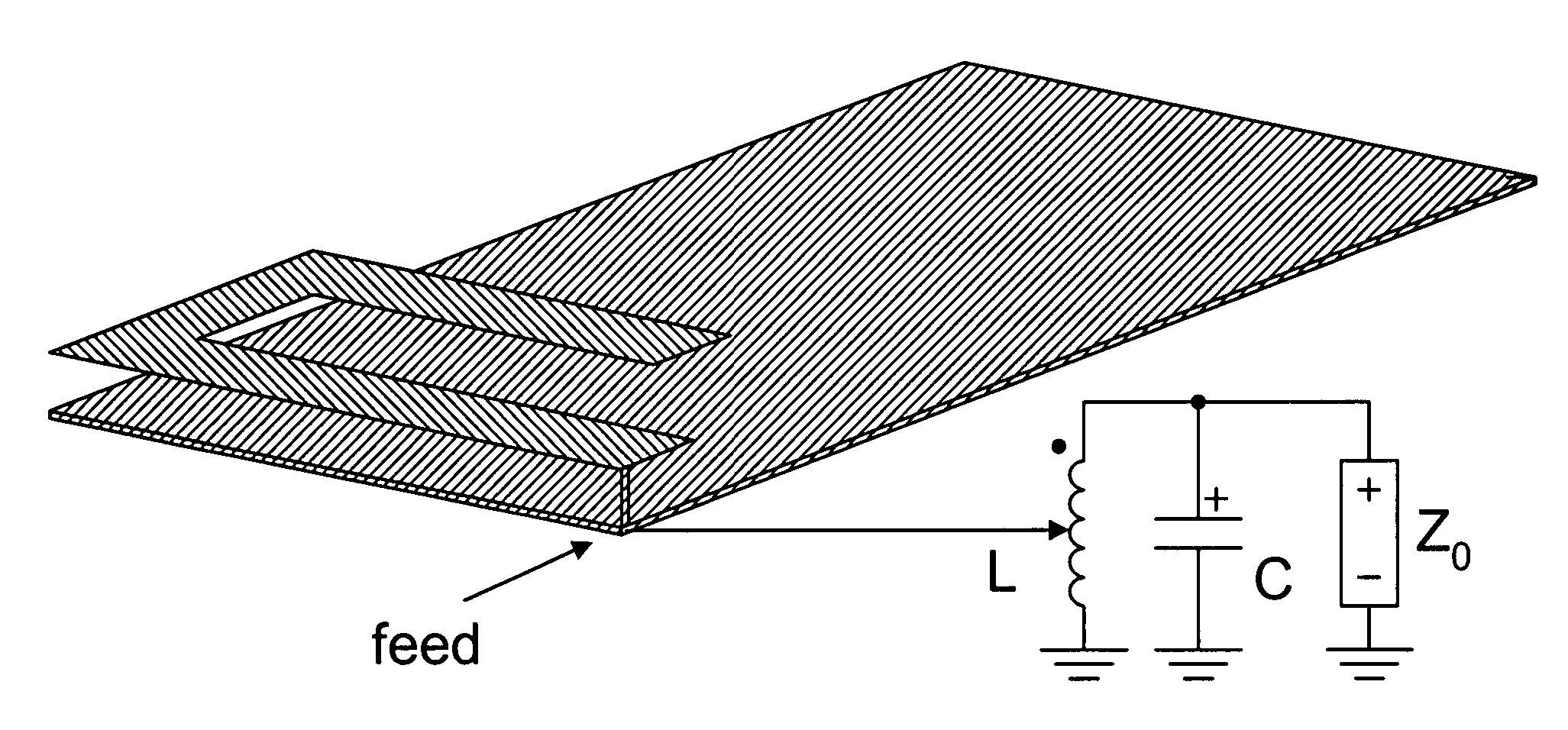
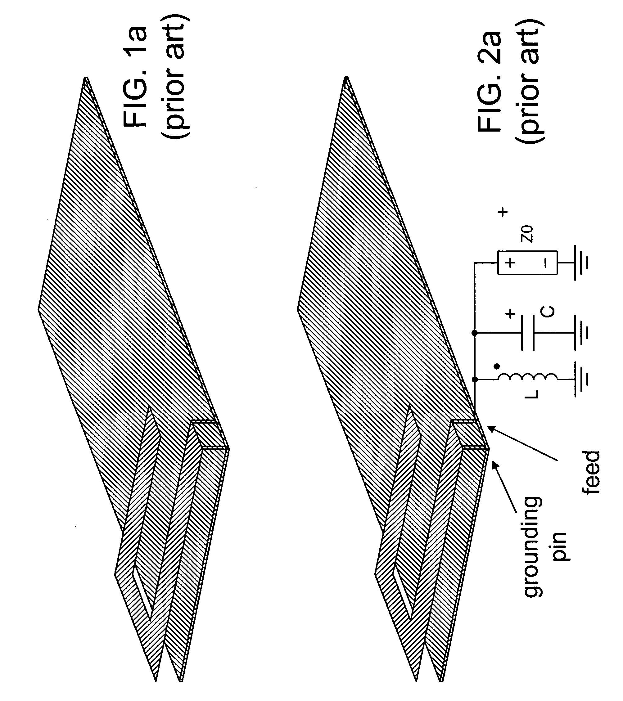
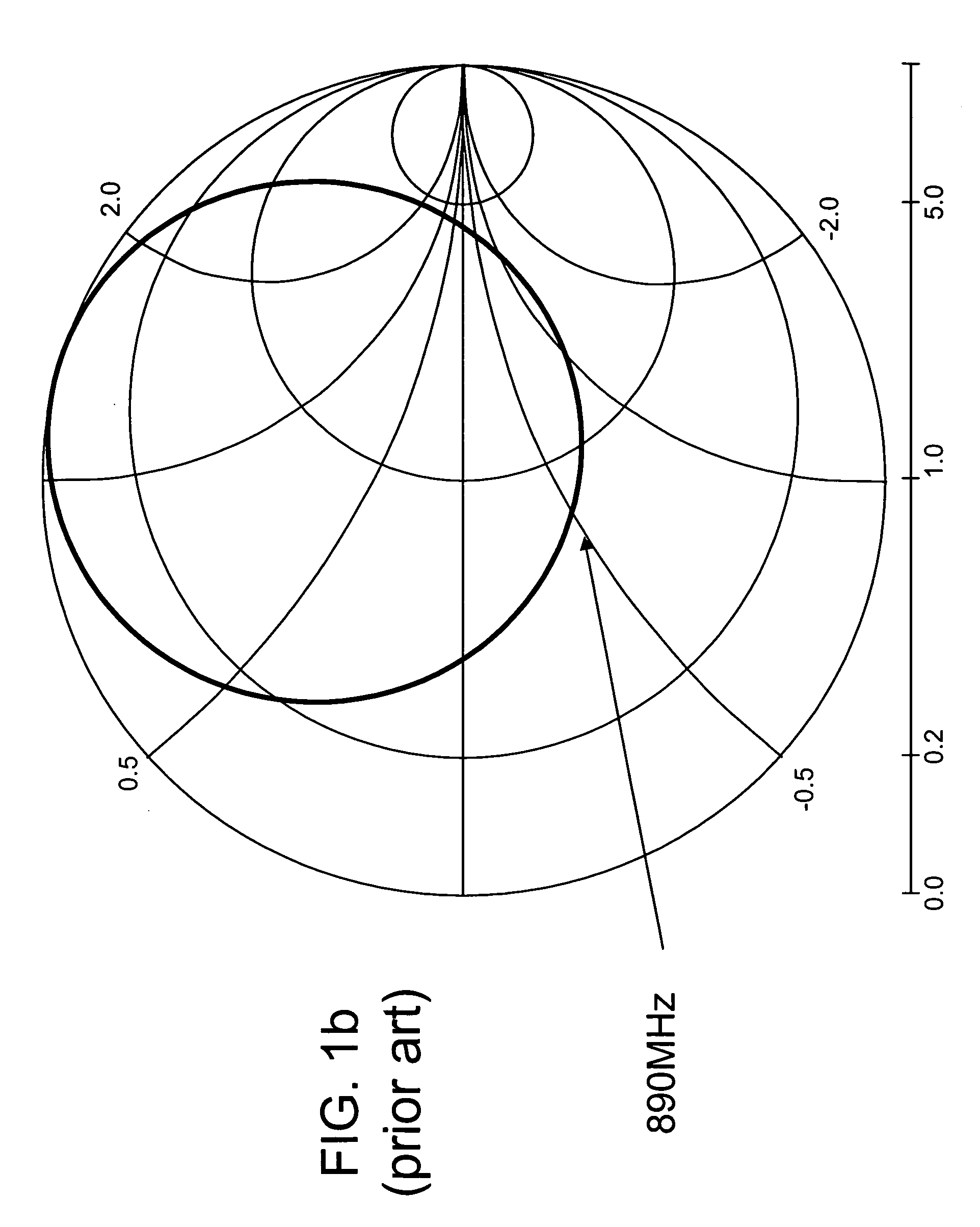
[0023] A conventional single-resonant PIFA type antenna (see FIG. 1a) has a low inherent bandwidth. A typical response of the PIFA type antenna is shown in FIG. 1b. It is possible to widen the bandwidth of a single-frequency, single-resonant PIFA type antenna by adding a parallel resonant network at the feed point of the PIFA, as shown in FIG. 2a. However, the PIFA must be modified to have about 20 ohms real impedance at the center frequency, as a simple resonance circuit cannot transform the impedance level of the antenna at the series-resonant frequency. This means that the impedance of the matched antenna on the series resonant (center) frequency is the same as the impedance of the antenna element itself on the series resonant frequency. This limits the use of a simple resonant circuit on an antenna element whose impedance level is moderate (˜20 ohms) at the center frequency. A typical response of the modified PIFA plotted on a Smith Chart is shown in FIG. 2b. The desired dual-re...


PUM


Abstract

A wide-band antenna comprises a series-resonant antenna and a resonant circuit. The antenna has a radiative element and a feed pin. The resonant circuit comprises an inductive element connected to the feed pin and a capacitor connected in parallel to the inductive element, which has a center tap for adjusting the impedance of the resonant circuit relative to the antenna impedance. The antenna can be a low-impedance PILA, a helix, monopole, whip, stub or loop antenna. The wide-band antenna can be used for the low (1 GHz range) or high (2 GHz range) band. The antenna can be made to simultaneously cover both 850 & 900 bands with the ground plane small enough to be implemented in a mobile phone or the like. The center tap is either connected to the feed of the antenna or connected to an RF front-end dependent upon the impedance level of the antenna element.

Description

FIELD OF THE INVENTION [0001] The present invention generally relates to a mobile phone antenna and, more particularly, to wide-band antennas whose bandwidth is increased by a resonant circuit. BACKGROUND OF THE INVENTION [0002] Typical 50 ohm low-band (850 & 900) planar inverted-F antennas (PIFAs) used in mobile phones have a single resonance and, consequently, a low bandwidth in the order of 50-60 MHz. Standard PIFA implementations are not capable of simultaneously covering both 850 band and 900 band (with a total required bandwidth of 136 MHz, from 824 MHz to 960 MHz). Available bandwidth could be increased by using a longer ground-plane or a higher antenna, but in most cases the ground plane length is limited to 100 mm and the antenna should be no higher than 5-6 mm. In these cases, getting enough bandwidth for both 850 and 900 is not possible without the use of load switching, for example. In 2 GHz area, it is possible to use a parasitic element in standard PIFA implementations...

Claims


Application Information

Patent Timeline
Patent Type & Authority Applications(United States)
IPC IPC(8): H01Q1/38
CPCH01Q1/243H01Q1/38H01Q7/00H01Q9/42H01Q9/0442H01Q9/36H01Q9/0421
Inventor RANTA, TERO
Owner WSOU INVESTMENTS LLC
Why Eureka
Try Eureka