Multi-camera system and method

a multi-camera system and camera technology, applied in the field of multi-camera system and method, to achieve the effect of minimizing operational power and less manufacturing cos

Active Publication Date: 2007-03-29
APTINA IMAGING CORP
View PDF4 Cites 70 Cited by
  • Summary
  • Abstract
  • Description
  • Claims
  • Application Information

AI Technical Summary

Benefits of technology

[0010] With such a multi-camera system, two optical trains and feeding analog signals into a single processing block is a more efficient way of realizing a multi-camera system. Such a system saves implementation space with only having one processing block. Further, manufacturing costs are less with only one processing block as two distinct processing blocks

Problems solved by technology

Such a system saves implementation spac

Method used


Image

  • Multi-camera system and method
  • Multi-camera system and method
  • Multi-camera system and method

Examples


Embodiment Construction

[0016] The following discussion is presented to enable a person skilled in the art to make and use the invention. The general principles described herein may be applied to embodiments and applications other than those detailed above without departing from the spirit and scope of the present invention. The present invention is not intended to be limited to the embodiments shown, but is to be accorded the widest scope consistent with the principles and features disclosed or suggested herein.

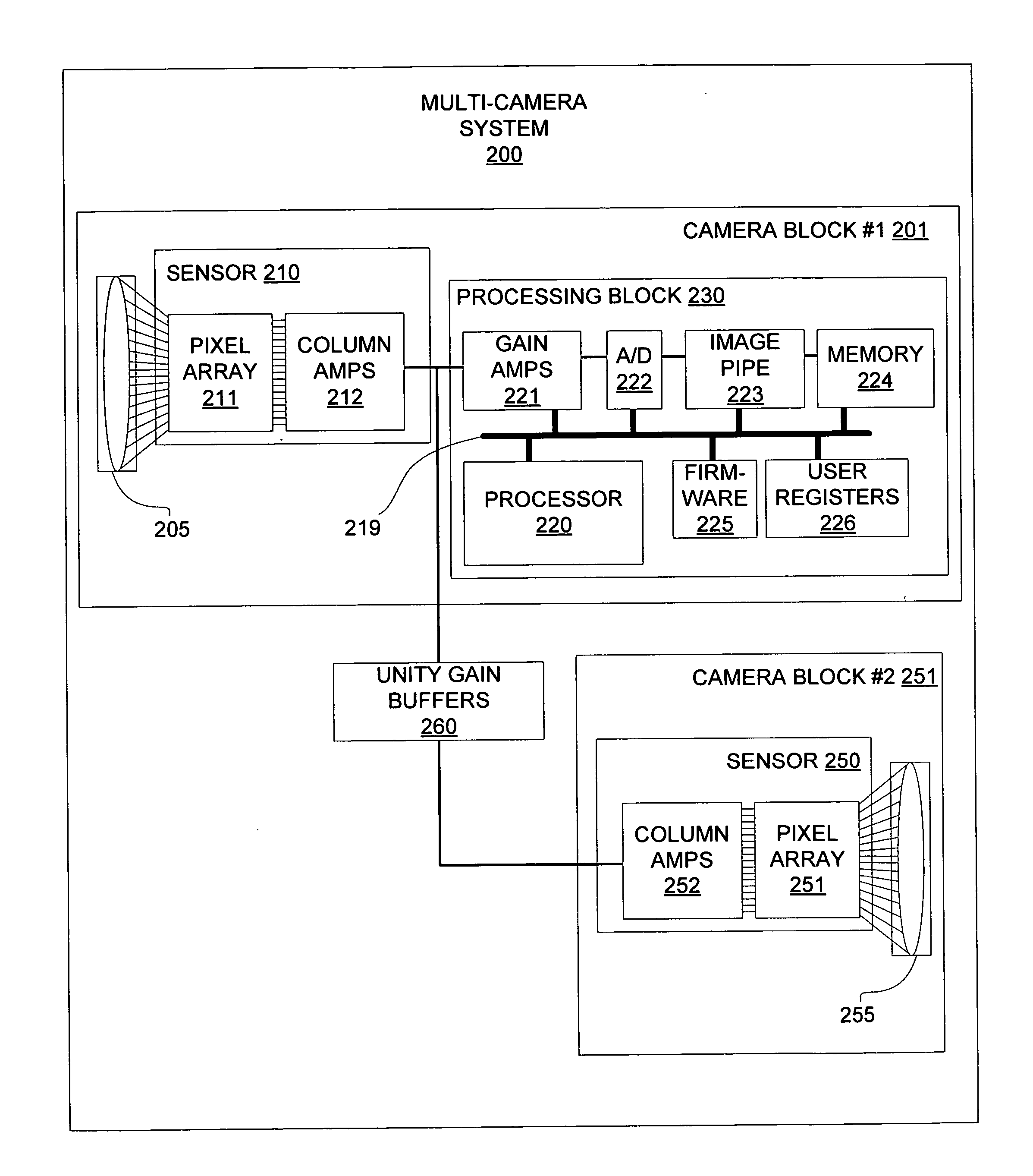
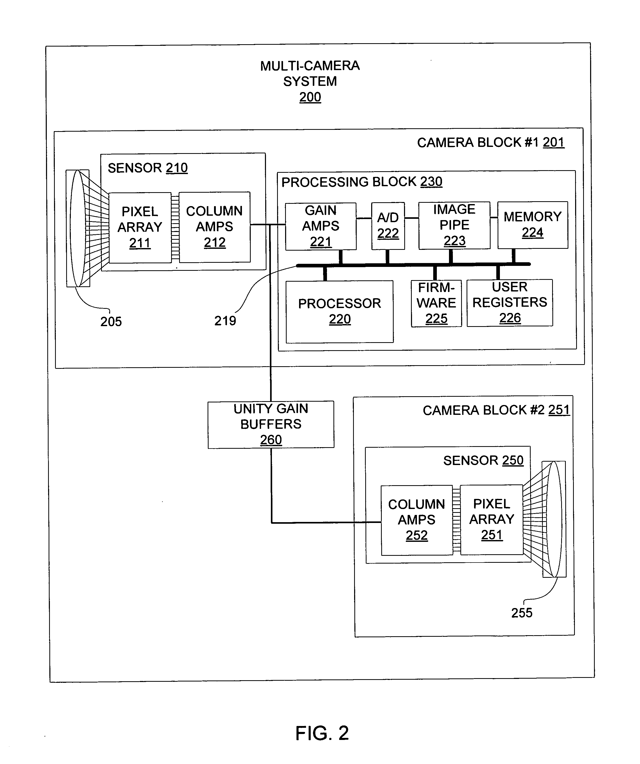
[0017]FIG. 2 is a block diagram of a multi-camera system 200 having two optical trains 205 and 255 pointed in different directions in accordance with an embodiment of the invention. In this embodiment, a first sensor 210 (associated with a first optical train 205) and a second sensor 250 (associated with a second optical train 255) are coupled to a processing block 230. The first sensor 210 and the processing block 230 may comprise a first camera block 201 while the second sensor 251 may be part o...


PUM


Abstract

A system and method for realizing a multi-camera system having two optical paths with a single processing path for the two optical paths. Such a multi-camera system typically includes a first image-capture device associated with a first optical train wherein the first image-capture device is typically pointed in a first direction (i.e., away from the user). The multi-camera system further includes a second image-capture device having a second optical train wherein the second image-capture device is typically pointed in a second direction (i.e., toward the user). The multi-camera system further includes a single processing block coupled to the first image-capture device and the second image-capture device. The processing block is typically operable to process image data captured at each image-capture device.

Description

BACKGROUND OF THE INVENTION [0001] Digital cameras and digital video cameras are becoming more prevalent in various electronic devices of today's electronics. It is common for cameras to be included in mobile phones, handheld devices, and portable / laptop computers. Because such digital cameras and digital video cameras are becoming cheaper to manufacture and are being realized in smaller packages, the demand for devices to include such cameras is increasing. As a result, more and more functionality for these cameras system is also being demanded. [0002] For example, cameras that are mounted to laptop computers, mobile phones and the like have typically been mounted in a fixed position such that any focal path of an optical train associated with the camera system was set relative to the device. That is, to point the camera in a different direction, the entire device needs to be maneuvered. Thus, a laptop computer having a camera pointing straight out of the view screen would require ...

Claims


Application Information

Patent Timeline
IPC IPC(8): H04N5/225
CPCH04N1/00307H04N1/00347H04N5/2251H04N2201/0084H04N2101/00H04N2201/001H04N2201/0063H04N5/2258H04N23/45
Inventor MENTZER, RAY A.
Owner APTINA IMAGING CORP
Why Eureka
Try Eureka