Variable threshold bipolar signal peak detector

a detector and bipolar signal technology, applied in the field of signal peak detectors, can solve the problems of increasing the likelihood of read signal distortion, introducing distortion in the read signal, and prolonging the event duration

Inactive Publication Date: 2007-03-29
AVAGO TECH INT SALES PTE LTD
View PDF17 Cites 19 Cited by
  • Summary
  • Abstract
  • Description
  • Claims
  • Application Information

AI Technical Summary

Problems solved by technology

However, the reduced fly height introduces an increased likelihood of read signal distortion due to thermal interaction between the head and the disk.
More particularly, changes in head temperature as the head flies over the disk surface, referred to as thermal asperities, introduce distortion in the read signals.
As contaminates and disk surface corrosion build-up with use of the disk drive, the event duration lengthens.
These effects further reduce the capabilities of a disk drive to reliably store and retrieve user data over its operational life.
Localized media anomalies can also cause problems in the storage and recov

Method used


Image

  • Variable threshold bipolar signal peak detector
  • Variable threshold bipolar signal peak detector
  • Variable threshold bipolar signal peak detector

Examples


Embodiment Construction

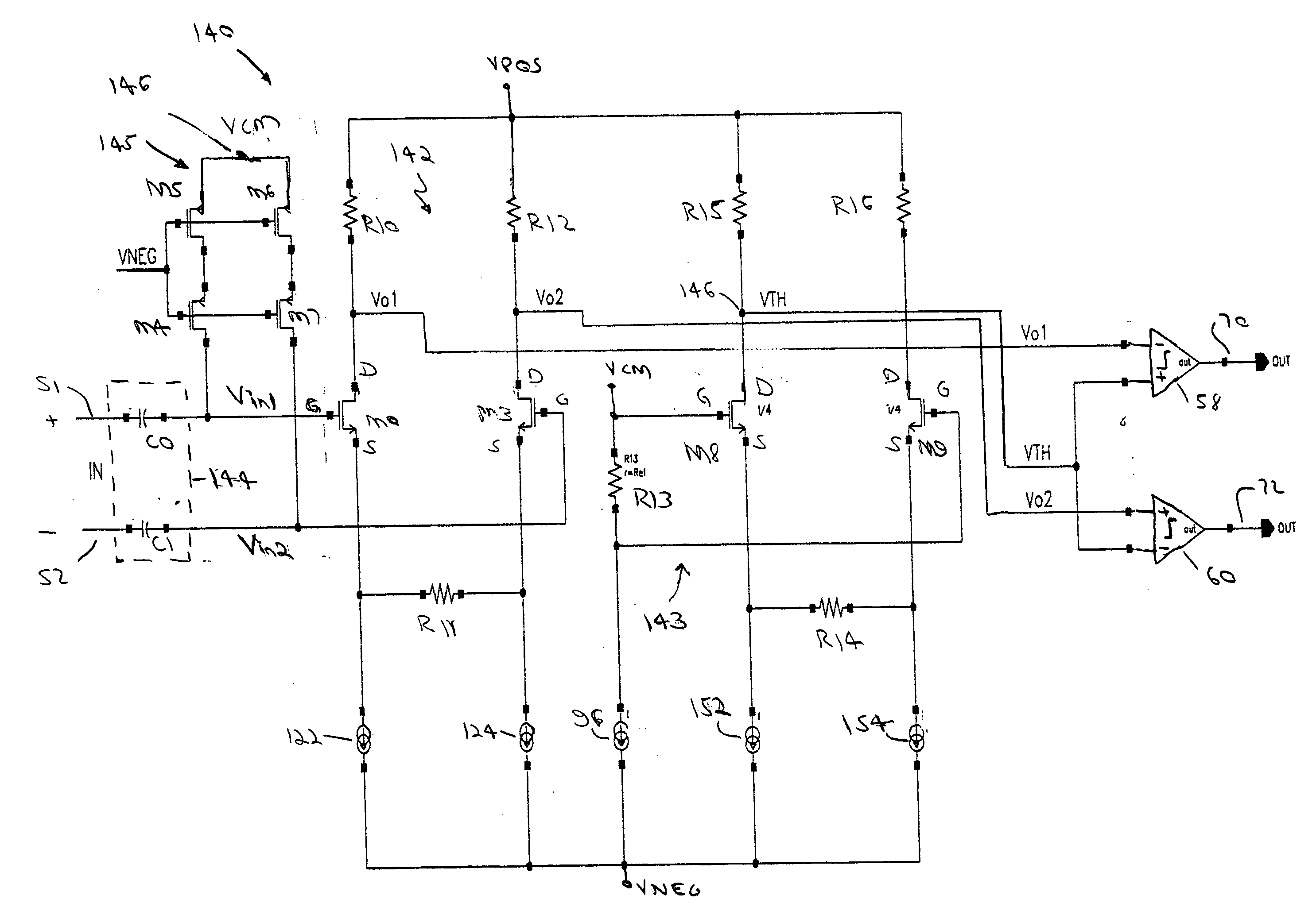
[0046] Before describing in detail the particular variable peak detector circuit and method related thereto according to the present invention, it should be observed that the present invention resides in a novel and non-obvious combination of structural elements and process steps. Accordingly, these elements and process steps have been represented by conventional elements and steps in the drawings and specification, wherein elements and process steps conventionally known in the art are described in lesser detail and elements and steps pertinent to understanding the invention are described with greater detail.

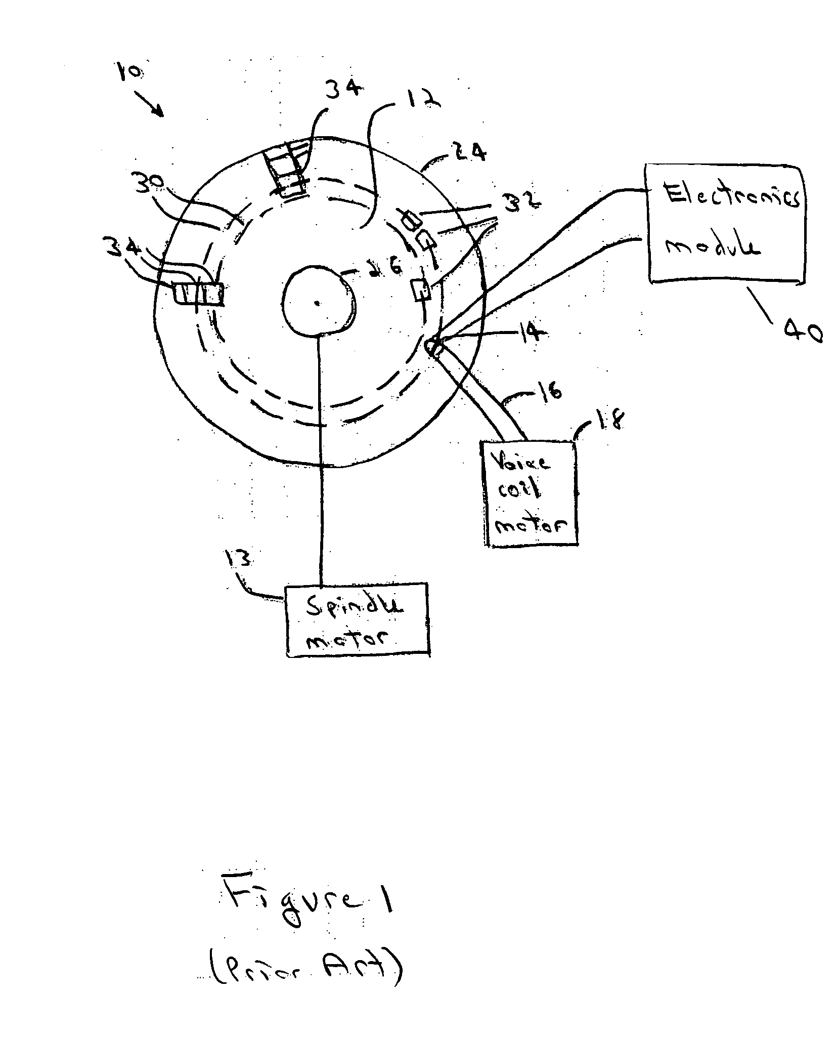
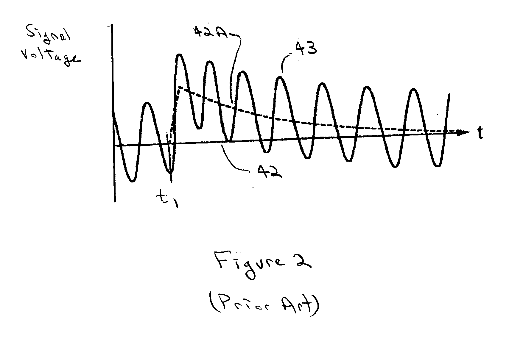
[0047] The present invention is useful for detecting signal excursions that exceed a predetermined threshold, including excursions caused by media anomalies and thermal asperity events, while reading data from a disk drive data storage system.

[0048]FIG. 5 illustrates an embodiment of a signal peak detector circuit 140 comprising a differential input amplifier 142, a differenti...


PUM


Abstract

A method and apparatus for detecting signal peaks caused by a thermal asperity event in a magnetic recording media to reduce data reading errors introduced by the thermal asperity event. A common mode voltage is determined for differential signals representing data bits read from the magnetic recording media and a threshold voltage produced responsive to the common mode voltage. A comparator determines if either of the differential signals exceeds the threshold voltage, thereby indicating the occurrence of a thermal asperity event.

Description

FIELD OF THE INVENTION [0001] The present invention relates generally to signal peak detectors and more particularly to variable threshold bipolar signal peak detectors and associated methods of comparing an input signal to a predetermined value. BACKGROUND OF THE INVENTION [0002] Disc drive storage systems are commonly used for storing data in electronic products ranging from digital cameras to computer systems. A disk drive comprises a head assembly and an electronics assembly conventionally attached to the head assembly for controlling head operation and providing a communication link between the head assembly and a host device served by the disk drive. The disk drive further comprises a disk having a data-recording surface for storing information therein. The disk is rotated at a constant speed while a closed loop servo system controls head position. The head assembly further comprises a read head for reading data from the recording surface and a write head for writing data to t...

Claims


Application Information

Patent Timeline
IPC IPC(8): G11B5/02G11B5/09
CPCG11B5/09G11B20/10203G11B2220/2516H03F1/52H03F2203/45074H03F3/45475H03F2200/435H03F2200/447H03F2200/78H03F3/45197
Inventor AEMIREDDY, ARVIND R.MALKA, RONENGLEASON, JEFFREY A.O'BRIEN, SCOTT M.
Owner AVAGO TECH INT SALES PTE LTD
Why Eureka
Try Eureka