Method and system for automatic vision inspection and classification of microarray slides

a microarray and automatic vision technology, applied in image enhancement, instruments, image data processing, etc., can solve the problems of affecting the interpretation of array images, the task of translating images, and the difficulty of table linking intensity values to each gene, so as to achieve low cost

Inactive Publication Date: 2007-03-29
NANYANG POLYTECHNIC
View PDF10 Cites 7 Cited by
  • Summary
  • Abstract
  • Description
  • Claims
  • Application Information

AI Technical Summary

Benefits of technology

[0014] Accordingly, one object of the present invention is to provide an inspection and classification system and method that inspect microarray slides automatically without user's intervention.

Problems solved by technology

However, the task of translating an image of spots with varying intensities into a table linking intensity values to each gene has been impeded by microarray technology challenges.
These fluctuations may be caused by many factors such as printing, hybridisation, and slide-surface chemistry factors, and can significantly affect the interpretation of an array image.
Actually, a small manufacturing defect in the same batch of arrays could affect the data analysis of specific genes.
Unfortunately, even best printing- parameters are subjected to variations of print tips, environmental factors, and the like.
In addition, random errors do occur, introducing extra variations into spots.
Another challenge for microarray technology is that it needs to process and analyse numerous images where a single image may contain thousands of spots.
The procedure becomes cumbersome when hundreds of microarray images need to be processed, as is the case in high-throughput screening.
Any approach involving even the smallest human efforts per spot is certainly impractical at this scale.
However, microarray slides and fully automated microarray slide machine with vision inspection capability are expensive.

Method used


Image

  • Method and system for automatic vision inspection and classification of microarray slides
  • Method and system for automatic vision inspection and classification of microarray slides
  • Method and system for automatic vision inspection and classification of microarray slides

Examples


Embodiment Construction

[0027] Unless defined otherwise, all technical and scientific terms used herein have the same meaning as commonly understood by one of ordinary skill in the art to which this invention belongs.

[0028] Throughout this application, where publications are referenced, the disclosures of these publications are hereby incorporated by reference, in their entireties, into this application in order to more fully describe the state of art to which this invention pertains.

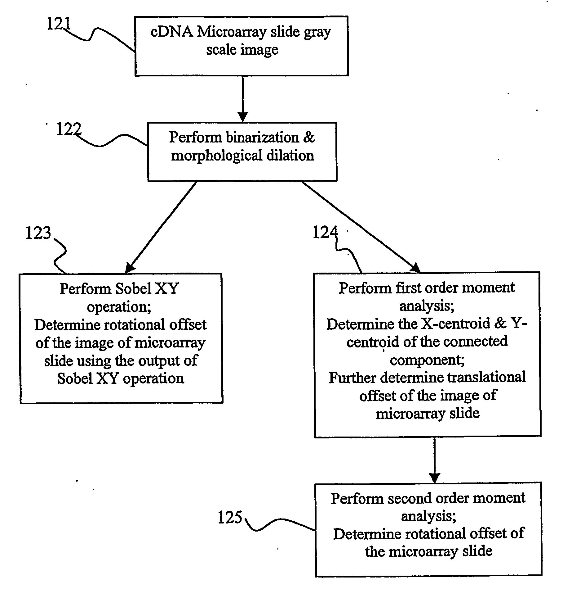
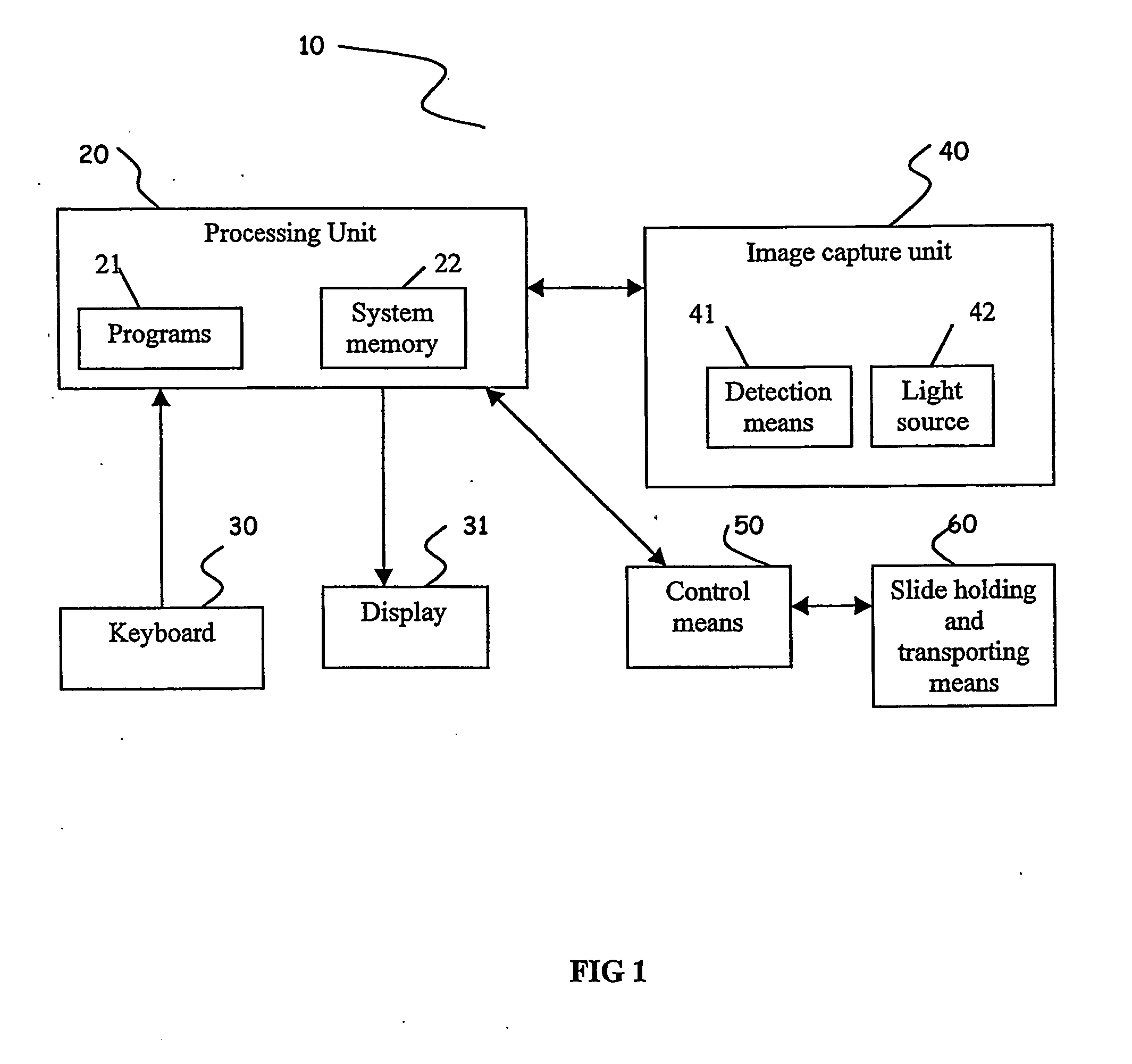
[0029] Referring to FIG. 1, an image-based vision inspection and classification system 10 includes a processing unit 20, a keyboard 30, a display 31, an image capture unit 40, a control means 50, and a slide holding and transporting means 60. The processing unit 20 is electrically connected to the keyboard 30, the display 31, the image capture unit 40, and the control means 50 via separate bus lines. The processing unit 20 includes application programs 21 that are used to execute the vision inspection and classification, and...


PUM


Abstract

The present invention provides a unique low cost vision inspection and classification system and methods for automatic inspection and classification of a microarray slide without manual intervention. The method first performs morphological dilation operation several times such that internal microarray spots are merged as a big connected component; then, the orientation of the merged spots, with respect to the X-axis and Y-axis is computed by computing the angle of the external boundaries of the connected component using Sobel XY operators for both edges and orientation determination, or using the moment-based algorithm for direct orientation determination; and the translational offset is determined by finding the X and Y centroids of the connected component. Moreover, the present invention provides threshold methods for classifying spots into normal spots, weak spots, missing spots, or overlapping spots.

Description

FIELD OF THE INVENTION [0001] The present invention relates generally to microarray technology, and more particularly to automated inspection and classification systems for microarray slides and methods of inspection and classification using the automated inspection and classification systems. BACKGROUND OF THE INVENTIION [0002] Microarray technology revolutionizes the ways by which genes and their functions are understood. Diverse applications of the microarray technology include profiling of gene expressions, classifying of tumors and cancers, cloning of genes, identifying of cancer genes, and discovering of therapeutic molecules. [0003] Microarray technology employs microarray slides to assay hundreds and thousands of interested targets simultaneously. For the instance of gene expression profiling, a microarray slide contains arrays of immobilized DNA samples, often called spots. The spots are usually probed by two dye-tagged or radioactively labelled cDNAs. These cDNAs are made ...

Claims


Application Information

Patent Timeline
Patent Type & Authority Applications(United States)
IPC IPC(8): G06K9/00G06T7/00G16B25/00G06T7/60G06V20/50
CPCG06F19/20G06K9/00G06T2207/30072G06T7/004G06T7/0012G06T7/70G16B25/00G06V2201/04G06V20/50G06V10/443G06V10/457G06F18/00
Inventor CHING, WEE SOON
Owner NANYANG POLYTECHNIC
Why Eureka
Try Eureka