Photo-sterilization

a technology of photo-sterilization and endodontics, applied in the field of endodontics or root canal therapy, can solve the problems of lingering latent infections, sensitivity to hot or cold foods and pain, and the repair itself dies, and achieves the effects of high light transmission, low cost, and unbreakabl

Inactive Publication Date: 2007-03-29
INTERLIGHT
View PDF20 Cites 46 Cited by
  • Summary
  • Abstract
  • Description
  • Claims
  • Application Information

AI Technical Summary

Benefits of technology

[0045] According to an additional aspect of the present invention, a surface of the optical fiber, which forms contact with the fluid, is machined to form a lens, for improved light diffusion.
[0176] The present invention successfully addresses the shortcomings of the presently known configurations by providing substances, devices, methods, and kits for photo-sterilization of a root canal, prior to and when performing endodontics, as well as periodically as post-endodontic prophylactic measures. The root-canal filling includes a light-transmitting element, operative as a diffuser, and methods are provided for communicating light to the diffuser, for disinfecting the walls of the root canals, by photo sterilization. The diffuser may be formed of silicone polymers, synthetic fused silica, quartz, or the like, and may be surrounded by a light-transmitting sealer. The diffuser may be incorporated with an endodontic post, or a specially designed post, which may be transparent and (or) hollow. In a preferred embodiment, the diffuser is formed of a light transmitting conical shell of Cyclic Olefin Copolymers (COC), filled with a fluid such as air, distilled water, or silicone oil. The COC shell is particularly advantageous as it is flexible, unbreakable, has high light transmission, conforms to the contours of the root canal, and is rather inexpensive to produce.

Problems solved by technology

When the pulp is diseased or injured and can't repair itself it dies.
The inflammation and infection may spread down the root canal, often causing sensitivity to hot or cold foods and pain.
However, in spite of careful and thorough disinfection, it may be incomplete, and latent infections may linger in the filled roots.

Method used


Image

  • Photo-sterilization
  • Photo-sterilization
  • Photo-sterilization

Examples


example 1

Single Bacteria Layer

[0369] Referring further to the drawings, FIGS. 18A-18E schematically illustrate a single-bacterial-layer, UV irradiation test.

[0370] As seen in FIGS. 18A and 18B, illustrating side and top views respectively, a bottom of a petri dish 200 was covered with a highly diluted bacterium solution 202, to a thickness just sufficient to wet it. It was known by statistical evaluation, that at that thickness, bacterium solution 202 contained only a single layer of bacteria.

[0371] A plurality of petri dishes 200 were prepared in this manner, and one was kept as a control.

[0372] As seen in FIG. 18C, except for the control dish, each petri dish 200 was placed in a Bio-Link Irradiator 204, for irradiation under a UV light 206, produced by a series of mercury lamps 208.

[0373] Each petri dish was irradiated at a different irradiation density, for example, 0.001 Joul / cm2, 0.002 Joul / cm2, 0.003 Joul / cm2, up to about 0.01 Joul / cm2.

[0374] As seen in FIGS. 18D, after irradiati...

example 2

Multi Bacteria Layer

[0378] Referring further to the drawings, FIGS. 20A-20D schematically illustrate a multi-bacterial-layer, UV irradiation test. The purpose of the multi-bacterial-layer was to evaluate the protective effect (screening effect) of the outermost bacterial layers over inner bacterial layers, from irradiation.

[0379] As seen in FIG. 20A, to imitate the effect of protective bacterial layers, a multi-layer setup 212 was constructed as follows: petri dish 200, with highly diluted bacterium solution 202, to a thickness just sufficient to wet it, was covered with a second solution 218, of a height and concentration of several bacterial layers. Second solution 218 was placed in a glass container formed of top and bottom neutral density filters 214, whose absorption factor of UV light was known, so that the absorption effect of the glass container could be taken into account. Spacers 216 were glued to the two neutral density filters 212, and the inner space, defined therein,...

example 3

Intra-Canal UV Irradiation Test

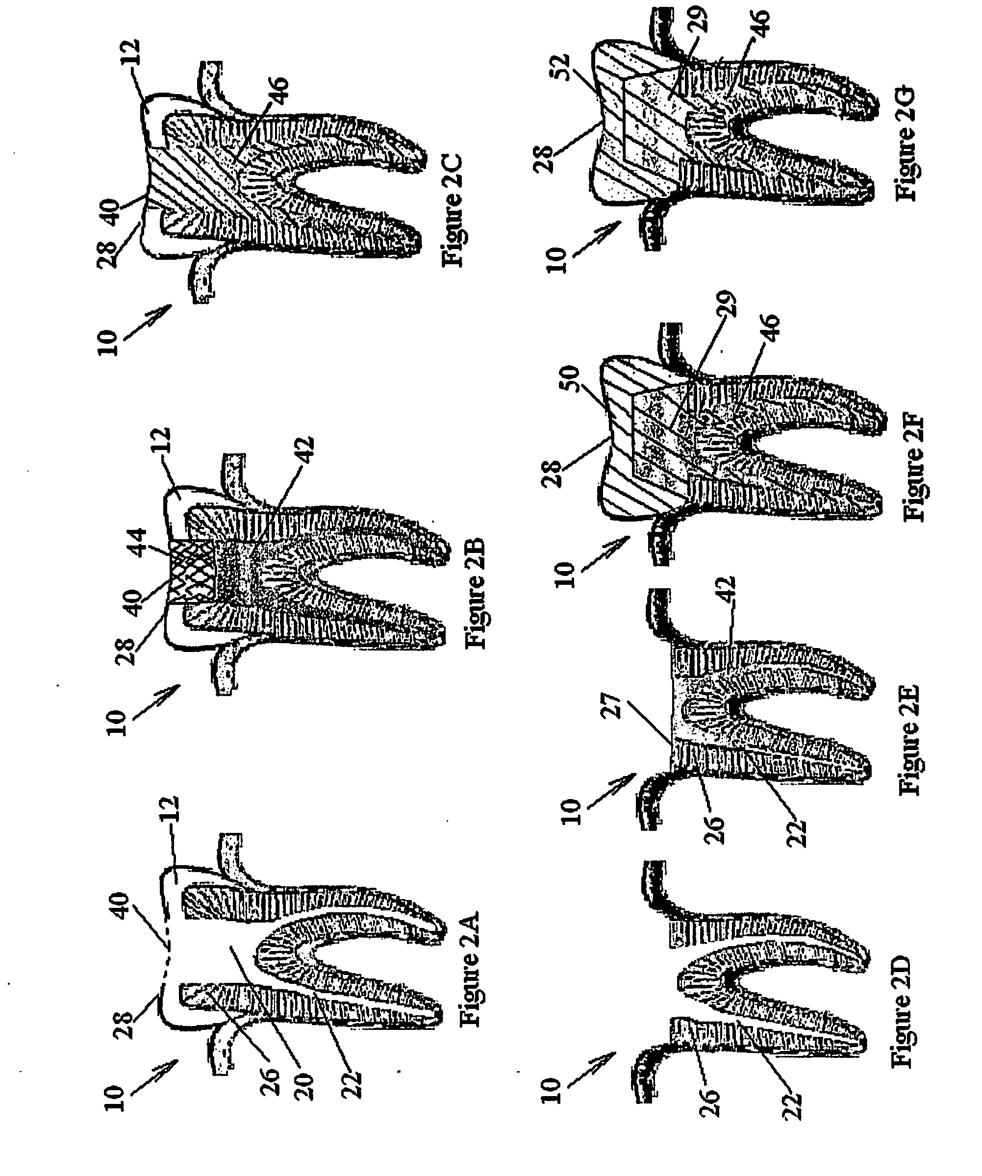
[0385] Referring further to the drawings, FIGS. 21A-21H schematically illustrate an intra-canal UV irradiation test, using a diffuser, in accordance with the present invention and in a manner similar to that taught, for example, by FIG. 7B, hereinabove.

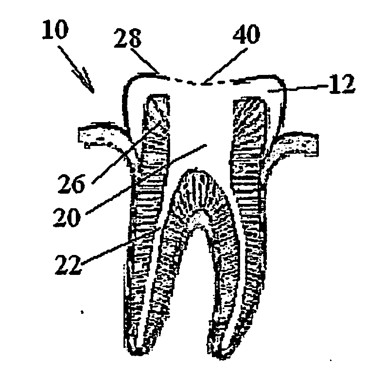
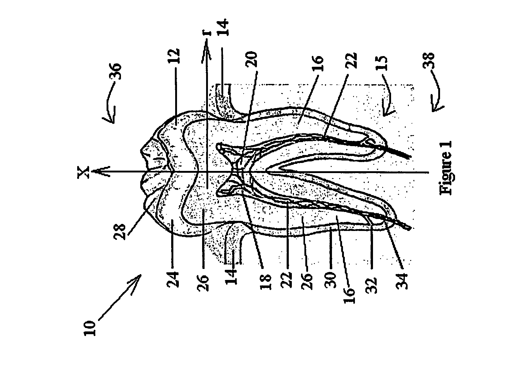
[0386] As seen in FIG. 21A, root canals 222 of a dog tooth 220 were cleaned. Tooth 220 was then placed in an autoclave, for sterilization.

[0387] As seen in FIG. 21B, a medium 224 containing bacteria was introduced into root canals 222 of tooth 220 and allowed to incubate for a period of two days.

[0388] As seen in FIG. 21C, after incubation, a control sample of bacterial medium is 224 was taken from root canal 222, and placed in petri dish 200, to a single bacterial thickness, forming a control perti dish.

[0389] As seen in FIG. 21D, root canals 222 were irradiated via diffuser 72, coupled to light source 62 of a mercury-lamp ultraviolet light, as taught in conjunction with FIG. 7B, hereinabove. Based...


PUM

PropertyMeasurementUnit
thickaaaaaaaaaa
thickaaaaaaaaaa
lengthaaaaaaaaaa

Abstract

The present invention provides substances, devices, methods, and kits for photo-sterilization of a root canal, prior to and when performing endodontics, as well as periodically as post-endodontic prophylactic measures. The root-canal filling includes a light-transmitting element, operative as a diffuser, and methods are provided for communicating light to the diffuser, for disinfecting the walls of the root canals, by photo sterilization. The diffuser may be formed of silicone polymers, synthetic fused silica, quartz or the like, and may be surrounded by a light-transmitting sealer. The diffuser may be incorporated with an endodontic post, or a specially designed post, which may be transparent and (or) hollow. In a preferred embodiment, the diffuser is formed of a light transmitting conical shell of Cyclic Olefin Copolymers (COC), filled with a fluid such as air, distilled water, or silicone oil.

Description

FIELD AND BACKGROUND OF THE INVENTION [0001] The present invention relates to endodontics, or root canal therapy, and, more particularly, to substances, devices, methods, and kits for photo-sterilization of a root canal, prior to and when performing endodontics, as well as periodically as post-endodontic prophylactic measures, and in cases of endodontic treatment failures. Additionally, the present invention relates to intracorporeal photo-sterilization of the internal walls of a catheter. FIG. 1 is a cross-sectional view of a tooth 10, as taught, for example, by http: / / www.dentalreview.com / tooth_anatomy.htm As seen in the figure, the basic parts of a tooth are: a crown 12, the portion of tooth above a gum 14, and a root or roots 16, which anchor the tooth in a jawbone 15. A pulp 18 is arranged within a pulp chamber 20 and within a root canal or root canals 22. [0002] Crown 12 is formed of an inner structure of dentine 26 and an external layer of enamel 24, which defines a chewing s...

Claims


Application Information

Patent Timeline
Patent Type & Authority Applications(United States)
IPC IPC(8): A61C5/02A61C5/04A61C5/08A61C19/00A61L
CPCA61C5/02A61C5/04A61C19/003A61N5/0603A61N5/0624A61N2005/067A61N2005/0631A61N2005/0659A61N2005/0661A61N2005/0662A61N2005/0606A61C5/40A61C5/50A61N5/067
Inventor GROSS, YOSSIBETTER, DANIELLEVY, BARUCHKEREN, DVIR
Owner INTERLIGHT
Why Eureka
Try Eureka