Wireless base station and communication method therefor

a wireless base station and communication method technology, applied in the direction of multiplex communication, polarisation/directional diversity, transmission monitoring, etc., can solve the problem of inability to form desired patterns, and achieve the effect of reducing bandwidth and simplifying operations such as adjustment and maintenance of wireless base stations

Inactive Publication Date: 2007-03-29
HITACHI LTD
View PDF9 Cites 81 Cited by
  • Summary
  • Abstract
  • Description
  • Claims
  • Application Information

AI Technical Summary

Benefits of technology

[0033] According to the present invention, since the compensation system for eliminating the deviations is localized in the remote unit, operations such as adjustment and maintenance of the wireless base station are simplified. Further, since the amount of control information to be transmitted from the center unit to the remote unit through the optical fiber is small, the present invention can provide a wireless base station system that enables significant reduction of bandwidth necessary for the optical fiber section and capable of reducing the running costs.

Problems solved by technology

Therefore, even when transmission signals weighted by antenna element, a problem still occurs in that desired be an patterns cannot be formed as it is influenced by the phase rotation.

Method used


Image

  • Wireless base station and communication method therefor
  • Wireless base station and communication method therefor
  • Wireless base station and communication method therefor

Examples


first embodiment

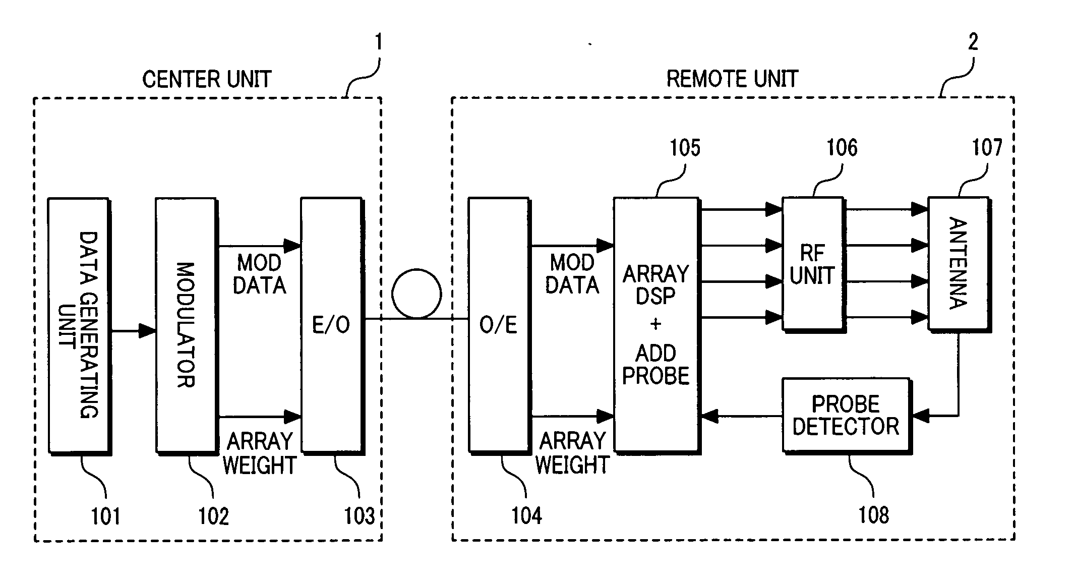
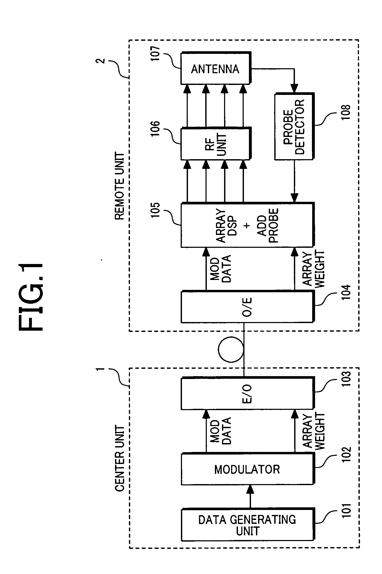
[0042]FIG. 1 is a configuration diagram showing a first embodiment of a wireless base station according to the present invention.

[0043] The base station comprises a center unit 1 and a remote unit 2 that are interconnected by an optical fiber. The base station shown here is used for networks of mobile wireless communication, such as represented by cellular communication. In the case where multiple base stations are requiring service area, multiple remote units 2 can be distributedly located, and multiple center units 1 connected to the remote units 2 can be concentrically located in a specific site. In addition, although not shown in the drawings, the configuration may be such that multiple remote units 2 are connected to a single center unit 1, and the transmission signal is distributed from the same center unit 1 to the respective remote units 2.

[0044] The remote unit 2 is a small apparatus that is placed on a building roof, a telegraph pole, or the like, and processes the trans...

second embodiment

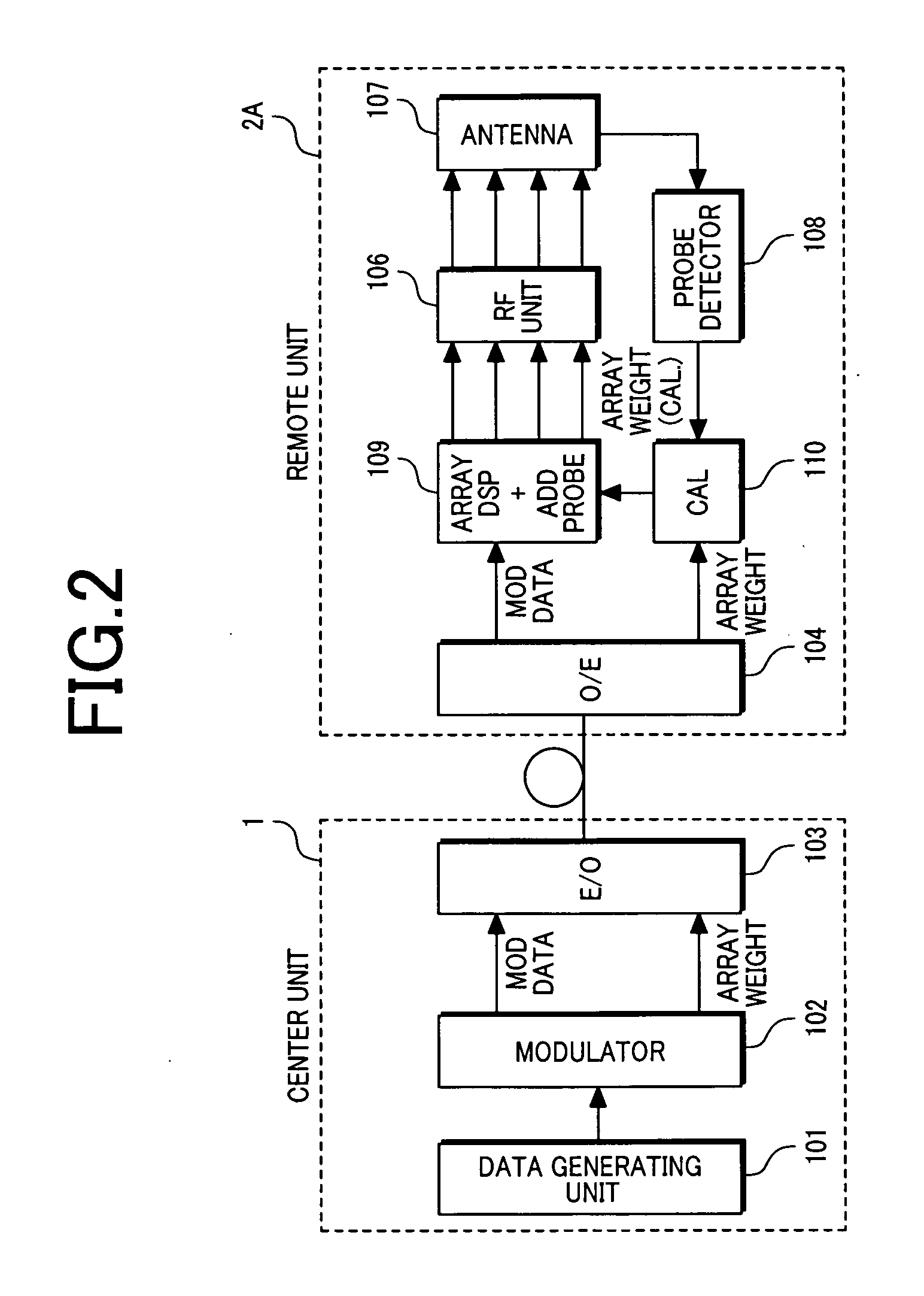
[0080]FIG. 2 is a configuration diagram showing a second embodiment of a wireless base station according to the present invention. The second embodiment is different from the first embodiment in the configuration of the remote unit.

[0081] In the present embodiment, the array processor unit 105 shown in FIG. 1 is divided into an array processor unit 109 for processing modulated transmission signal (MOD data) and a weight compensation unit 110 for compensating for array weights based on the output information from the probe detector 108.

[0082] The weight compensation unit 110 stores array weights output from the remote-unit optical interface 104 into a memory. The weight compensation unit 110 generates complex vector information for compensating for the phase or amplitude of an output signal from a specific antenna element based on output information from the remote-unit optical interface 104, and performs the multiplication between the array weights stored in the memory and the com...

third embodiment

[0086] As a third embodiment according to the present invention, FIG. 3 shows a configuration diagram of a wireless base station employing a multi-input multi-output (MIMO) technique.

[0087] In the MIMO type wireless base station, the streams of transmission signals are different from one another for the respective antenna elements. Therefore, plural streams of transmission signals corresponding to the respective antenna elements have to be generated when the base band modulation has been performed in a center unit 1B. For this reason, in the case of MIMO type wireless base station, different from the case of the first and second embodiment, the center unit 1B cannot transmit a base band signal common to the plurality of antenna elements to the remote unit 2 through the optical fiber.

[0088] In the MIMO type wireless base station has a problem to be solved particularly when level deviations occurred across transmission signals, such that compensation has to be performed to attain eq...


PUM


Abstract

In a wireless base station comprising a center unit, and a remote unit provided with an array antenna and connected to the center unit through an optical fiber, the center unit outputs to the optical fiber a transmission signal in a base band state prior to array processing, the remote unit performs the array processing of transmission signals in accordance with array weights and converts the transmission signals into RF signals, thereby to localize the compensation for transmission signal deviations occurring among the antenna elements on the remote unit side.

Description

CLAIM OF PRIORITY [0001] The present application claims priority from Japanese application serial No. 2005-283795, filed on Sept. 29, 2005, the content of which is hereby incorporated by reference into this application. BACKGROUND OF THE INVENTION [0002] 1. Field of the Invention [0003] The present invention relates to a wireless base station and a communication method therefor. More specifically, the invention relates to a wireless base station separated into a center unit and a remote unit and to a communication method for communication between the center unit and the remote unit. [0004] 2. Description of Related Art [0005] In the field of wireless communication systems, while changing is demanded to the fourth generation, the data rate has been enhanced, and the communication area has become ubiquitous, such that a need is considered to increase for system configurations of the type including a large number of small base stations with relatively low transmission power. In additio...

Claims


Application Information

Patent Timeline
Patent Type & Authority Applications(United States)
IPC IPC(8): H04B1/38H04M1/00H04B7/06H04B7/10H04B10/00H04J14/00H04J14/02H04W88/08
CPCH04W88/085H01Q3/26H04B7/155
Inventor KUWAHARA, MIKIOTAIRA, MASANORI
Owner HITACHI LTD
Why Eureka
Try Eureka