Method for reducing code size of program in code memory

a technology of code memory and code size, applied in the computer system, can solve the problems of increasing manufacturing cost, reducing the code size of programs, and requiring a relatively higher manufacturing cost in memory, so as to and reduce the size of programs

Active Publication Date: 2007-03-29
SAMSUNG ELECTRONICS CO LTD
View PDF17 Cites 4 Cited by
  • Summary
  • Abstract
  • Description
  • Claims
  • Application Information

AI Technical Summary

Benefits of technology

[0017] Accordingly, the present invention solves the above-mentioned problems occurring in the prior art, and the present invention provides a method, apparatus, and medium for reducing the code size of a program by controlling the control flow of the program using software in a computer system.
[0018] An aspect of the present invention provides a method of reducing a size of a program in a code memory, the method including storing a first memory address of a first instruction in a first buffer when a software interrupt occurs while the first instruction having two operands including Offset and Length is being executed from among a plurality of instructions loaded in the code memory; changing the program counter register value to a second memory address which is obtained by adding the Offset to the first memory address; storing a second instruction, which is located at a position shifted from the second memory address by a value of the Length, in a second buffer; replacing the second instruction with a third instruction, which triggers a software interrupt; replacing the third instruction with the second instruction stored in the second buffer when a software interrupt occurs while the third instruction is being executed; and changing the current program counter register value of the code memory to a predetermined memory address next to the first memory address stored in the first buffer.
[0019] According to another aspect of the present invention, there is provided a method of reducing a size of a program in a code memory, the method including executing a first instruction having two operands including Offset and Length and a second instruction ordering a branch to a system function, from among a plurality of instructions loaded in the code memory; storing a first memory address of the second instruction in a first buffer; changing the program counter register value to a second memory address which is obtained by adding the Offset to the first memory address; storing a third instruction, which is located at a position shifted from the second memory address by a value of the Length, in a second buffer; replacing the third instruction with a fourth instruction ordering a branch to the system function; replacing the fourth instruction with the third instruction stored in the second buffer when the fourth instruction has been executed; and changing the current program counter register value to a predetermined memory address next to the first memory address stored in the first buffer.
[0020] According to still another aspect of the present invention, there is provided a method of reducing a size of a program in a code memory, the method including copying instructions, which are located between a first position indicated by Offset and a second position shifted from the first position by a value of Length, in a temporary buffer when a software interrupt occurs while a first instruction having two operands including the Offset and Length is being executed from among a plurality of instructions loaded in the code memory; inserting a second instruction, which orders a return to an instruction next to the first instruction, into a location next to the instructions copied in the temporary buffer; executing the instructions copied in the temporary buffer; and returning to the instruction next to the first instruction loaded in the code memory according to execution of the second instruction.
[0021] According to still another aspect of the present invention, there is provided a method of reducing a size of a program in a code memory, including copying instructions, which are represented as iterative instructions, in a temporary buffer when a software interrupt occurs while a first instruction, among a plurality of instructions loaded in the code memory, is being executed; inserting a second instruction, which orders a return to an instruction next to the first instruction, into a location next to the instructions copied in the temporary buffer; executing the instructions copied in the temporary buffer; and returning to the instruction next to the first instruction loaded in the code memory according to execution of the second instruction.

Problems solved by technology

Among the above components of the computer system, the memory, such as SRAM or DRAM, generally requires a relatively higher manufacturing cost.
However, although the hardware compression technique can reduce the time required for data restoration, the manufacturing cost may be increased because it requires the hardware restorer, so the hardware compression technique may not be suitable for a computer system, which is installed in the electronic appliance in order to control the operation of the electronic appliance in real time.
However, although the software compression technique does not require additional hardware, such as a compressor, a relatively long time is necessary to compress and restore the data because the software compression technique is slower than the hardware compressor.
Therefore, both the software compression technique and the hardware compression technique may not be suitable for the computer system embedded in the electronic appliance.
However, the ISA modification scheme requires a mass-storage processor, such as ARM or MIPS, and such a mass-storage processor is not suitable for some applications.
This may require a change of hardware, causing an increase in the development cost of the microcomputer system equipped in the electronic appliance.

Method used


Image

  • Method for reducing code size of program in code memory
  • Method for reducing code size of program in code memory
  • Method for reducing code size of program in code memory

Examples


exemplary embodiment 1

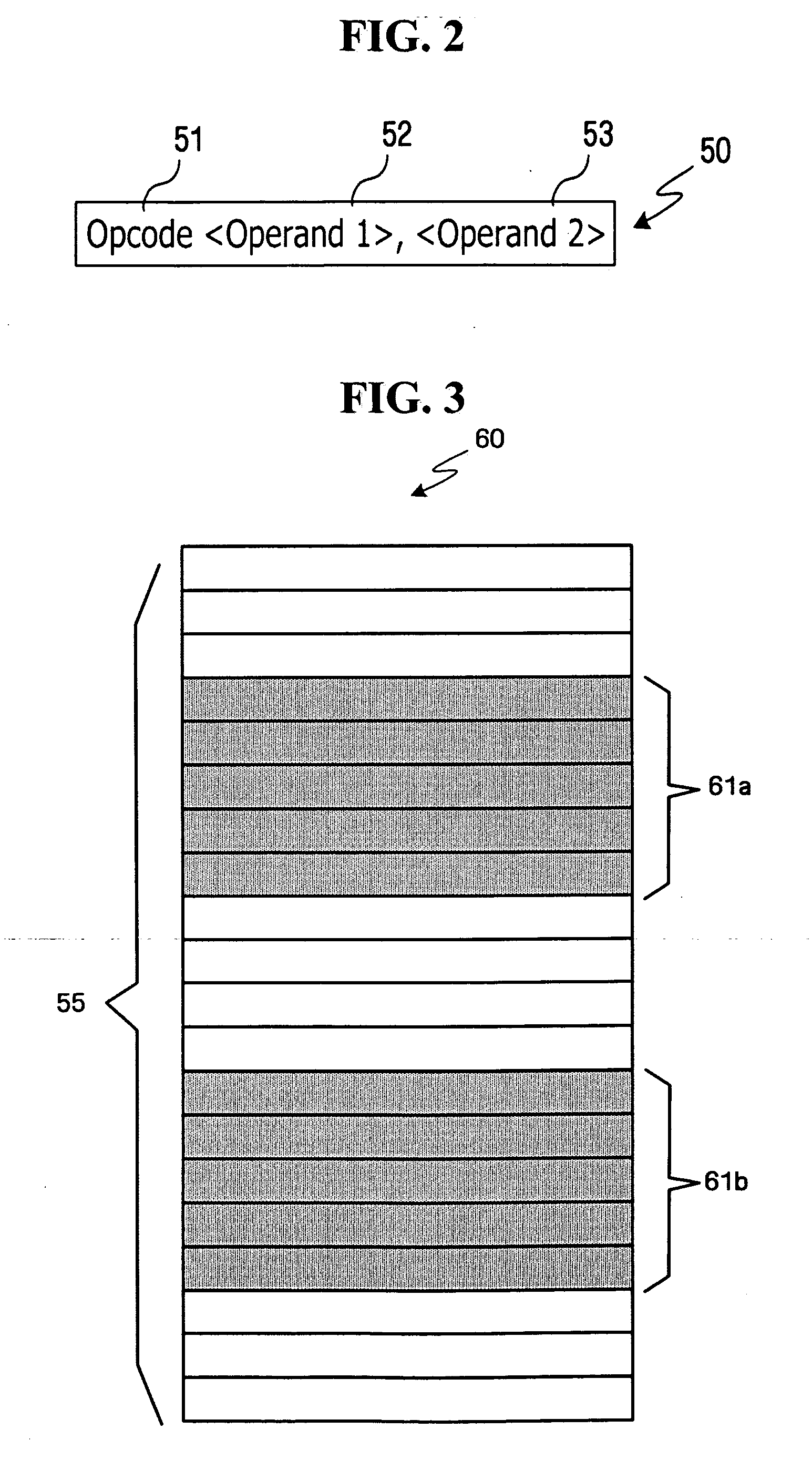
[0051]FIG. 4 is a view showing a structure of a code memory 70 according to a first exemplary embodiment of the present invention. Different from the code memory 60 shown in FIG. 3, the code memory 70 shown in FIG. 4 has a compacted structure having no iterative instruction sets. In particular, the first instruction set 61a shown in FIG. 3 is removed and an “Echo” instruction 71 is added thereto. In addition, an original instruction located next to the second instruction set 61b is replaced with a predetermined instruction 72, and the predetermined instruction 72 is again replaced with the original instruction later.

[0052] The instruction 71“Echo , ” is located at the fourth position of the code memory 70, that is, the first position of the instruction set 61a shown in FIG. 3. The microprocessor 11 cannot recognize the “Echo” instruction 71. For this reason, an error may occur when executing the “Echo” instruction 71 caused by an undefined instruction, so that an exception handling...

exemplary embodiment 2

[0060]FIG. 5 is a view showing a structure of a code memory 80 according to a second exemplary embodiment of the present invention. Different from the first exemplary embodiment of the present invention in which the additional cost may occur because several cycles are added to the control flow of the microprocessor 11 due to the exception handling process, the second exemplary embodiment of the present invention may not cause the additional cost by removing the exception handling process.

[0061] As shown in FIG. 5, although the error may occur when the microprocessor 11 executes the Echo instruction 71, the microprocessor 11 executes a “Branch” instruction 81 without performing the exception handling procedure. The “Branch” instruction 81 represents the branch to the first system function, which has been previously defined.

[0062] The first system function is defined in such a manner that the first system function can perform the procedure similar to the exception handling procedure...

exemplary embodiment 3

[0066]FIG. 6 is a view showing a structure of a code memory 90 according to a third exemplary embodiment of the present invention. As shown in FIG. 6, the third exemplary embodiment of the present invention is partially modified from the first and second exemplary embodiments of the present invention. According to the third exemplary embodiment of the present invention, the branch instructions may not be modified by an exception handling unit of the operating system 21 or a system function, which has been previously defined. Instead, the instructions to be executed are stored in a temporary buffer 99 provided in the code memory 90 and then the instructions are executed after changing the addresses of the instructions corresponding to the positions of the instructions in the temporary buffer 99. The third exemplary embodiment of the present invention may be efficiently used when the original program includes a memory, such as the ROM 13, which cannot be corrected during execution.

[0...


PUM


Abstract

A method of reducing a code size of a program by controlling a control flow of the program using software in a computer system is disclosed. The method includes the steps of storing a first program count of a first instruction in a first buffer when an error occurs while the first instruction having an Operand including Offset and Length is being executed among a plurality of instructions loaded in the code memory, changing a current program count of the code memory to a second program count which is obtained by adding the Offset to the first program count, storing a second instruction, which is located at a position shifted from the second program count by a value of the Length, in a second buffer, replacing the second instruction with a third instruction, which is not recognized by a microprocessor, replacing the third instruction with the second instruction stored in the second buffer when an error occurs while the third instruction is being executed, and changing the current program count of the code memory to a predetermined program count next to the first program count stored in the first buffer.

Description

CROSS-REFERENCE TO RELATED APPLICATIONS [0001] This application claims the benefit of Korean Patent Application No. 10-2005-0088927 filed on Sep. 23, 2005 in the Korean Intellectual Property Office, the disclosure of which is incorporated herein by reference in its entirety. BACKGROUND OF THE INVENTION [0002] 1. Field of the Invention [0003] The present invention relates generally to a computer system, and more particularly to a method of reducing code size of a program by controlling the control flow of the program using software in a computer system including a microprocessor and a memory. [0004] 2. Description of the Related Art [0005] Portable devices or small-sized electronic appliances used in the office or at home, such as refrigerators, cleaners, printers or flash memory cards, are equipped with middleware that cooperates with a real time operating system in order to control devices installed in the electronic appliances, such as motors, in real time. Since electronic applia...

Claims


Application Information

Patent Timeline
Patent Type & Authority Applications(United States)
IPC IPC(8): G06F15/00G06F15/76
CPCG06F9/30058G06F9/30065G06F9/325G06F9/30178G06F9/445G06F9/44557G06F9/328G06F9/22G06F12/00
Inventor YIM, KEUN-SOOLEE, JAE-DONYOO, JEONG-JOONKANG, KYOUNG-HOPARK, JUNG-KEUNIM, CHAE-SEOKKIM, WOON-GEEBAEK, CHANG-WOO
Owner SAMSUNG ELECTRONICS CO LTD
Why Eureka
Try Eureka