Continuous process of roll-forming stamped sheet

a continuous process and stamping technology, applied in the direction of girders, bumpers, manufacturing tools, etc., can solve the problems of inability to change the material properties within the part, the inability to change the cross section along the length of the part, and the limitations of roll-forming

Inactive Publication Date: 2007-04-05
SHAPE CORP
View PDF41 Cites 51 Cited by
  • Summary
  • Abstract
  • Description
  • Claims
  • Application Information

AI Technical Summary

Benefits of technology

[0012] In still another aspect of the present invention, a method of forming a reinforcement beam comprises steps of providing a heater, providing a press including forming dies at a location downstream of the heater and also a cooling system associated with the press, and providing a roll-former having rolls in-line and downstream of the press. The method includes heating a strip of material, operating the dies to deform the strip of material by drawing the hot material and thereafter quickly cooling the material, and operating rolls of a roll-forming mill to receive the strip in a feed direction and shape edge portions of the deformed strip into a reinforcement beam.

Problems solved by technology

However, roll-forming has limitations, such as the inability to change material properties within the part and the inability to change the cross section along the length of the part.
The inability to change the cross section along the length of the part typically results in excessive material being used in areas where it is not needed to meet performance requirements in other areas where it is needed.
The excessive material also adds to the weight of the part and to material cost.
The inability to change the cross section of a roll-formed tubular beam along its length results in a tubular beam with a constant moment of inertia.
However, stamping operations are limited and generally less efficient than roll-forming since individual sheet blanks must be laterally moved and accurately positioned after each die stroke.
Also, dies cannot make tubular beams without significant difficulty or complexity, or with secondary operations.
Further, high strength and ultra high strength sheet material is very wearing on dies depending on the amount of shape deformation being imparted onto the sheet material and depending on a strength of the material.
However, the above-described hot stamping technique tends to be an intermittent “stop-and-go” process which historically is not considered to be well-suited for use in a continuous processes operating at relatively high line speeds (i.e. not well-suited for being used in-line with rollforming equipment).

Method used


Image

  • Continuous process of roll-forming stamped sheet
  • Continuous process of roll-forming stamped sheet
  • Continuous process of roll-forming stamped sheet

Examples


Embodiment Construction

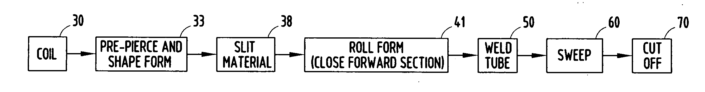
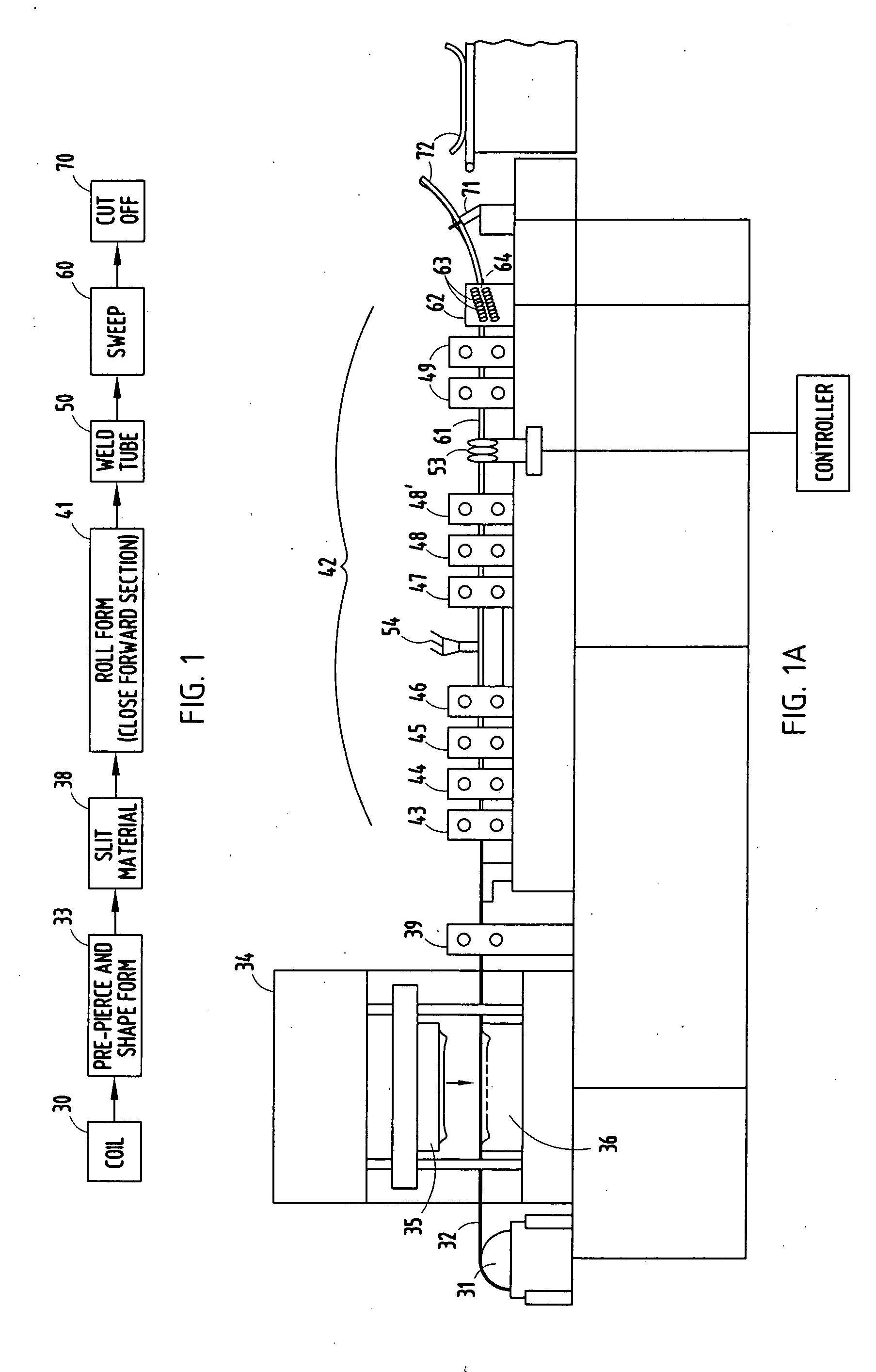
[0022] The current invention defines a way to produce roll-formed tubular beams with varying cross sections from high-strength sheet material, such as materials of over 80 ksi tensile strength and even ultra-high-strength steel of over 140 ksi tensile strength (sometimes called “UHSS” or “AUHSS” material). For example, a DP980 (DF140) material has successfully been used. The ability to change cross sections along the length of the beam is achieved by combining a pre-forming process via stamping with the roll-forming. The stamping process and roll-forming operations are done in-line and sequentially. Sequential processes in-line without the need for secondary handling results in a very cost efficient manufacturing process. The stamping press is used to pre-form material as well as pre-pierce the sheet material and add features before it travels through the roll-forming tooling. The stamping of the material while it is in the flat produces a shape with varying depth and geometry acros...


PUM

PropertyMeasurementUnit
temperatureaaaaaaaaaa
yield strengthaaaaaaaaaa
tensile strengthaaaaaaaaaa

Abstract

An apparatus includes a press with dies configured to deform a strip of material by drawing material primarily from a width direction, a slitter set to cut the deformed strip to a uniform desired width dimension, and a roll-former with rolls configured to shape linear portions of the deformed and now uniform-width strip into a continuous beam. The apparatus further includes a welder for welding abutting edges of the sheet together to form a permanent tube, a sweep station for imparting a longitudinal shape to the continuous beam, and a cut-off for cutting the continuous beam into segments useful as vehicle bumper beams. A controller controls timing of various components. The beam segments are optimized in specific regions for local strength and minimized weight, and features can be incorporated into the beam segments such as coplanar mounting surfaces.

Description

CROSS REFERENCE TO RELATED APPLICATIONS [0001] This is a continuation-in-part application of co-assigned, co-pending utility application Ser. No. 11 / 330,301, filed Feb. 11, 2006, entitled CONTINUOUS PROCESS OF ROLL-FORMING PRE-STAMPED VARYING SHAPES, which is turn claims benefit of provisional application Ser. No. 60 / 723,393, filed Oct. 4, 2005, entitled CONTINUOUS PROCESS OF ROLL-FORMING PRE-STAMPED VARYING SHAPESBACKGROUND [0002] The present invention relates to a continuous process of roll-forming pre-stamped varying shapes, and more particularly relates to a process combining a stamping / deforming process with a roll-forming apparatus to obtain advantages of both in a continuous process. [0003] The advantages associated with roll-forming have made roll-forming a preferred manufacturing method for many open structural sections and tubular structural sections. Automotive bumpers beams are one example of a product that has capitalized on the benefits of roll-forming to produce light...

Claims


Application Information

Patent Timeline
Patent Type & Authority Applications(United States)
IPC IPC(8): B21B15/00
CPCB21C37/0803B21C37/0815B21C37/083B21C37/155B21C37/185B21D5/12B60R19/18B60R2019/1826E04C3/07E04C2003/0439
Inventor HEATHERINGTON, DAVID
Owner SHAPE CORP
Why Eureka
Try Eureka