
Mobile terminal apparatus

a terminal and mobile technology, applied in the field of mobile terminal devices, can solve the problems of aforementioned noise becoming a considerable problem, noise occurring, noise being much louder, etc., and achieve the effect of suppressing nois

Inactive Publication Date: 2007-04-05
PANASONIC CORP
View PDF16 Cites 24 Cited by
  • Summary
  • Abstract
  • Description
  • Claims
  • Application Information

AI Technical Summary

Benefits of technology

[0043] According to the present invention, it is possible to obtain an effect that it is possible to provide mobile terminal apparatus capable of suppressing occurrence of noise while keeping required display capacity in accordance with the operation condition of the apparatus.

Problems solved by technology

This is because there occur problems in such a layout as follows.
Therefore, this frequency may be heard as noise (sounding) for human beings in the liquid crystal display panel engaging in display operation by the one-line inversion drive system.
Further, even in another system than the one-line inversion drive system, there occurs noise in the same manner as described above, when a drive system in which the frequency of signal waveform applied to electrodes becomes an audio frequency is used.
Thus, there has been a problem that there occurs a noise much louder than when the acrylic panel 512 is not charged.
As described previously, it is an essential problem to reduce the thickness of mobile terminal apparatus such as a cellular phone or the like.
As a result, the aforementioned noise becomes a considerable problem.
Therefore, occurrence of the aforementioned noise has been a grave problem in a liquid crystal display unit mounted on mobile terminal apparatus such as a cellular phone or the like, particularly in a liquid crystal display unit designed so that the liquid crystal display unit portion becomes thin.
The noise is an important problem particularly in a cellular phone or the like having a structure in which a display portion comes close to a user's ear when the cellular phone is in use.
However, the frame inversion drive generally has a problem in image quality.
Further, when a still picture is displayed, unevenness in the up / down direction of the display screen, crosstalk, flicker, etc. do not matter as compared with those in the frame inversion drive.
However, in the interlace drive, there are problems in image quality as follows.
That is, when a movie is being displayed, horizontal stripes appear on the display screen, or a user viewing the display screen has a feeling of wrongness.

Method used


Image

  • Mobile terminal apparatus
  • Mobile terminal apparatus
  • Mobile terminal apparatus

Examples


first embodiment

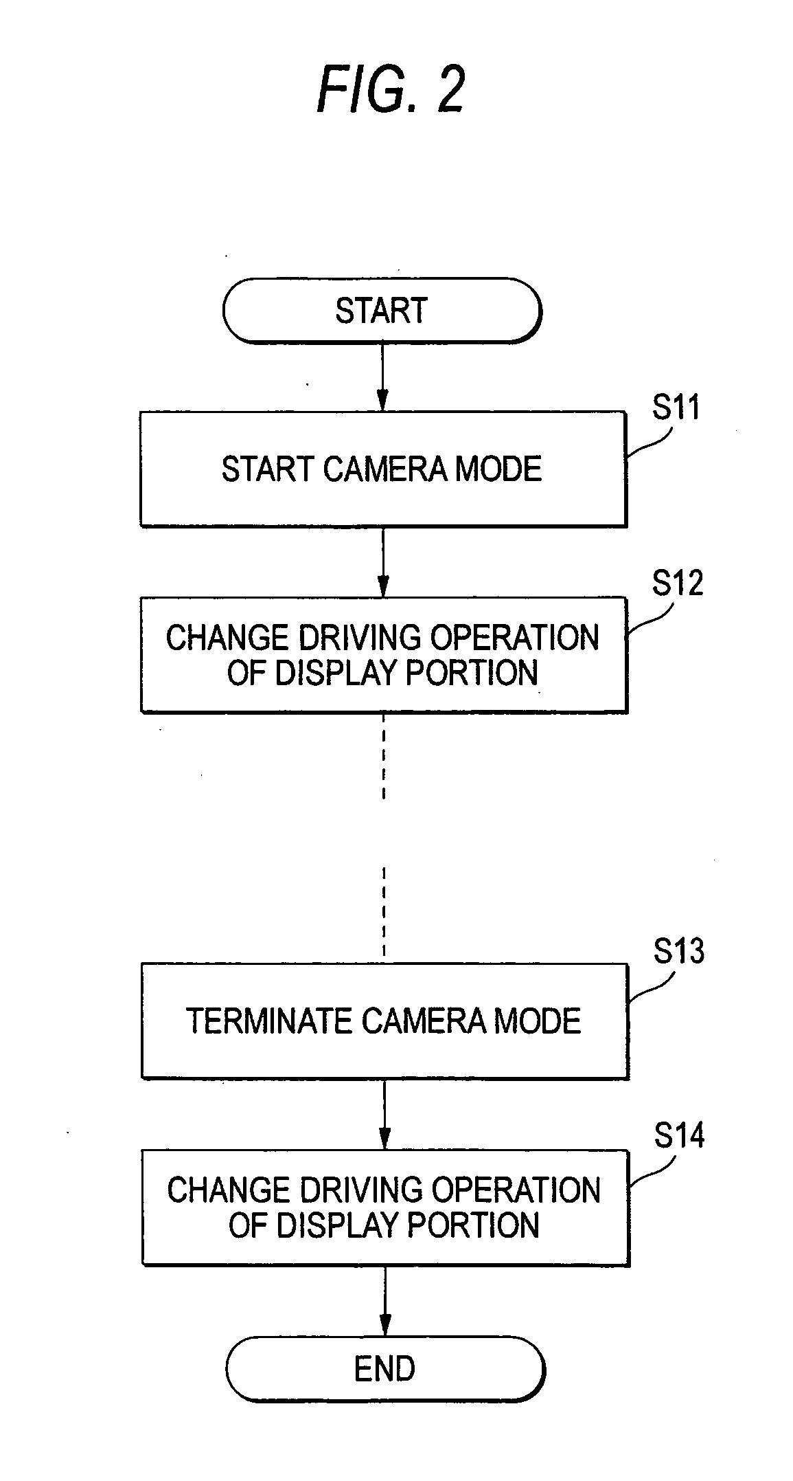
[0075]FIG. 2 is a flow chart showing the operation of mobile terminal apparatus according to a first embodiment. In the first embodiment, the driving operation of the display portion 20 is changed at the time of start of a camera mode for operating the camera 21, such as a camera photographing mode, a videophone communication mode, or the like. Thus, driving operation for giving priority to the image quality is performed when an image photographed by the camera 21 is displayed. When the camera mode is terminated, the driving operation of the display portion 20 is changed into driving operation for suppressing noise of the display portion 20.

[0076] That is, as soon as the camera mode is started by an operation input of the operation portion 18 or the like from the user (Step S11), the control portion 16 changes the driving operation of the display portion 20 into driving operation for improving the image quality of an image displayed on the display portion 20 (Step S12). Then, as so...

second embodiment

[0092]FIG. 6 is a timing chart for explaining the operation of mobile terminal apparatus according to a second embodiment. This FIG. 6 shows the condition of line scanning in a display portion and the timing of changing the driving operation thereof.

[0093] The second embodiment shows an example of timing of changing the driving operation of the display portion 20 in the liquid crystal display unit. When the driving operation is changed in the middle of displaying an image on the display portion 20, there is a fear that the display screen is disordered for a moment, or an image different from a normal one is displayed. Therefore, in order to prevent such a failure in a displayed image when the drive is changed, the drive is changed in a period when the screen of the liquid crystal display device is not actually scanned.

[0094] Specifically, as shown in FIG. 6, after scanning all the lines from the first line to the N-th line, the driving operation of the drive system, the driving fr...

third embodiment

[0098]FIG. 7 is a flow chart showing the operation of mobile terminal apparatus according to a third embodiment. The third embodiment shows another example for making the change of the driving operation so unostentatious that the user cannot be aware of it. This third embodiment may be used when the aforementioned drive change control according to the second embodiment cannot be used or when it takes several milliseconds or longer time to change the drive.

[0099] In the third embodiment, the contents of display are changed by rewriting the screen when the driving operation of the display portion 20 is changed. That is, the screen is rewritten as to the contents of display in the display portion 20 (Step S21). After that, as soon as the camera mode is started (Step S22), the control portion 16 changes the driving operation of the display portion 20 into the driving operation in which the image quality of an image displayed on the display portion 20 is improved (Step S23). Then, immed...


PUM


Abstract

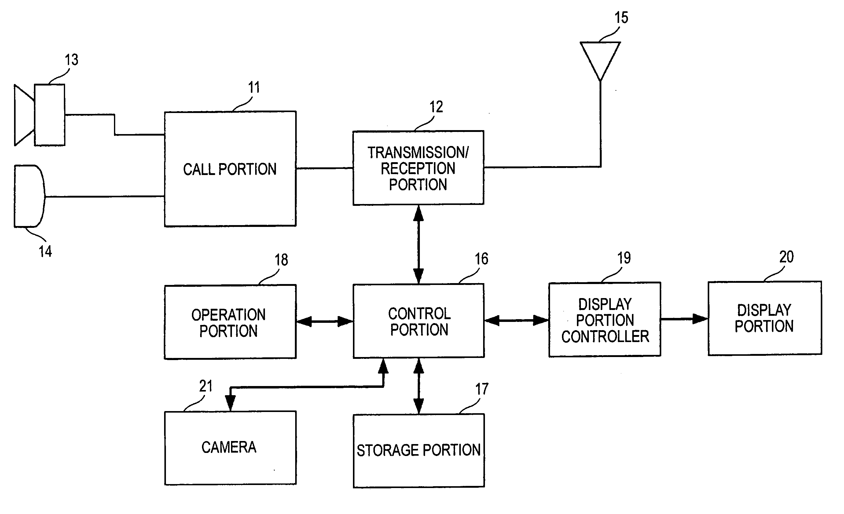
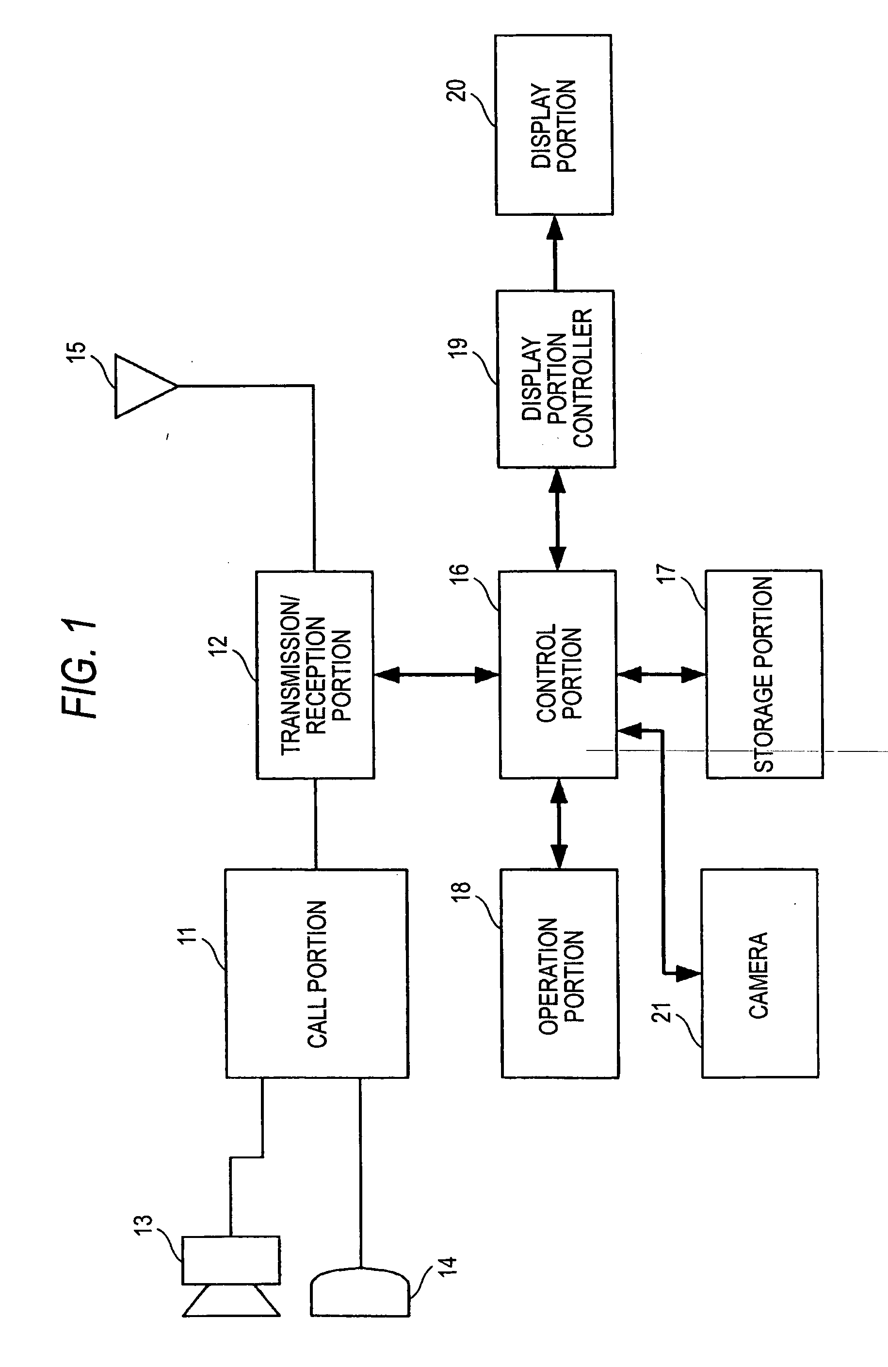
The present invention is to provide mobile terminal apparatus capable of suppressing occurrence of noise while keeping required display capacity in accordance with the operation condition of the apparatus. A control portion 16 and a display portion controller 19 control driving of a display portion 20 comprised of a liquid crystal display unit, and change the driving operation such as a drive system, a driving frequency, etc. into a suitable driving condition in accordance with the operation condition of the apparatus. For example, driving operation giving priority to the image quality of an image displayed on the display portion 20 is performed using sequential scanning drive such as one-line inversion drive when a movie is displayed in a camera operation mode or the like. Thus, visibility is improved. In another operation mode such as a voice call mode, driving operation giving priority to the acoustic characteristic is performed using interlaced scanning drive such as interlace drive so as to suppress noise caused by the display portion 20. Thus, a good use environment is secured.

Description

TECHNICAL FIELD [0001] The present invention relates to mobile terminal apparatus having a display unit such as a liquid crystal display unit or the like. BACKGROUND ART [0002] In recent years, liquid crystal display units have been often used as display units in mobile terminal apparatus such as mobile information terminals, cellular phones, small-size information equipments, etc. Users obtain necessary information from contents displayed on these display units. As for such a display unit used in mobile terminal apparatus, it is requested to make a display panel thinner to meet the demand of reduction in size and weight. [0003]FIG. 12 is a longitudinal sectional view showing an example of the configuration of a display portion of a related-art liquid crystal display unit applied to mobile terminal apparatus. In the liquid crystal display unit, a liquid crystal display panel 5 is disposed correspondingly to a display window 514 opened in a housing 511 forming a body of the mobile te...

Claims


Application Information

Patent Timeline
Patent Type & Authority Applications(United States)
IPC IPC(8): G09G3/36
CPCG09G3/3614G09G2310/0224G09G2310/0254G09G2320/0261G09G2330/021H04M2250/52H04R19/02H04R2499/11H04W52/027Y02D30/70
Inventor SATOU, ICHIROUKATAGIRI, ATSUSHI
Owner PANASONIC CORP
Learn More