Nozzle members, compositions and methods for micro-fluid ejection heads

a technology of nozzle members and nozzles, which is applied in the direction of magnetic recording, data recording, instruments, etc., can solve the problems of high manufacturing cost inability to provide suitable reentrant nozzles in conventional photoimaging and development techniques, and inability to meet the needs of microfluid ejection heads, etc., to achieve improved speed and quality, improve the effect of speed and quality

Active Publication Date: 2007-04-05
SLINGSHOT PRINTING LLC
View PDF15 Cites 20 Cited by
  • Summary
  • Abstract
  • Description
  • Claims
  • Application Information

AI Technical Summary

Benefits of technology

[0002] Micro-fluid ejection devices, such as ink jet printers continue to evolve as the technology for ink jet printing continues to improve to provide higher speed, higher quality prin

Problems solved by technology

However, the improvement in speed and quality does not come without a price.
The micro-fluid ejection heads are more costly to manufacture because of tighter alignment tolerances.
However, minor imperfections in the substrate or nozzle plate components of the ejection head or improper alignment of the parts has a significant impact on the performance of the ejection heads.
While the use of an imaged photoresist layer improves alignment of the flow features to the ejection actuat

Method used


Image

  • Nozzle members, compositions and methods for micro-fluid ejection heads
  • Nozzle members, compositions and methods for micro-fluid ejection heads
  • Nozzle members, compositions and methods for micro-fluid ejection heads

Examples


Embodiment Construction

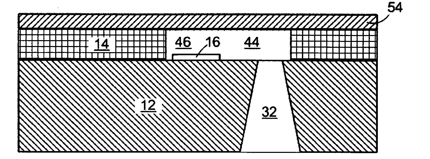
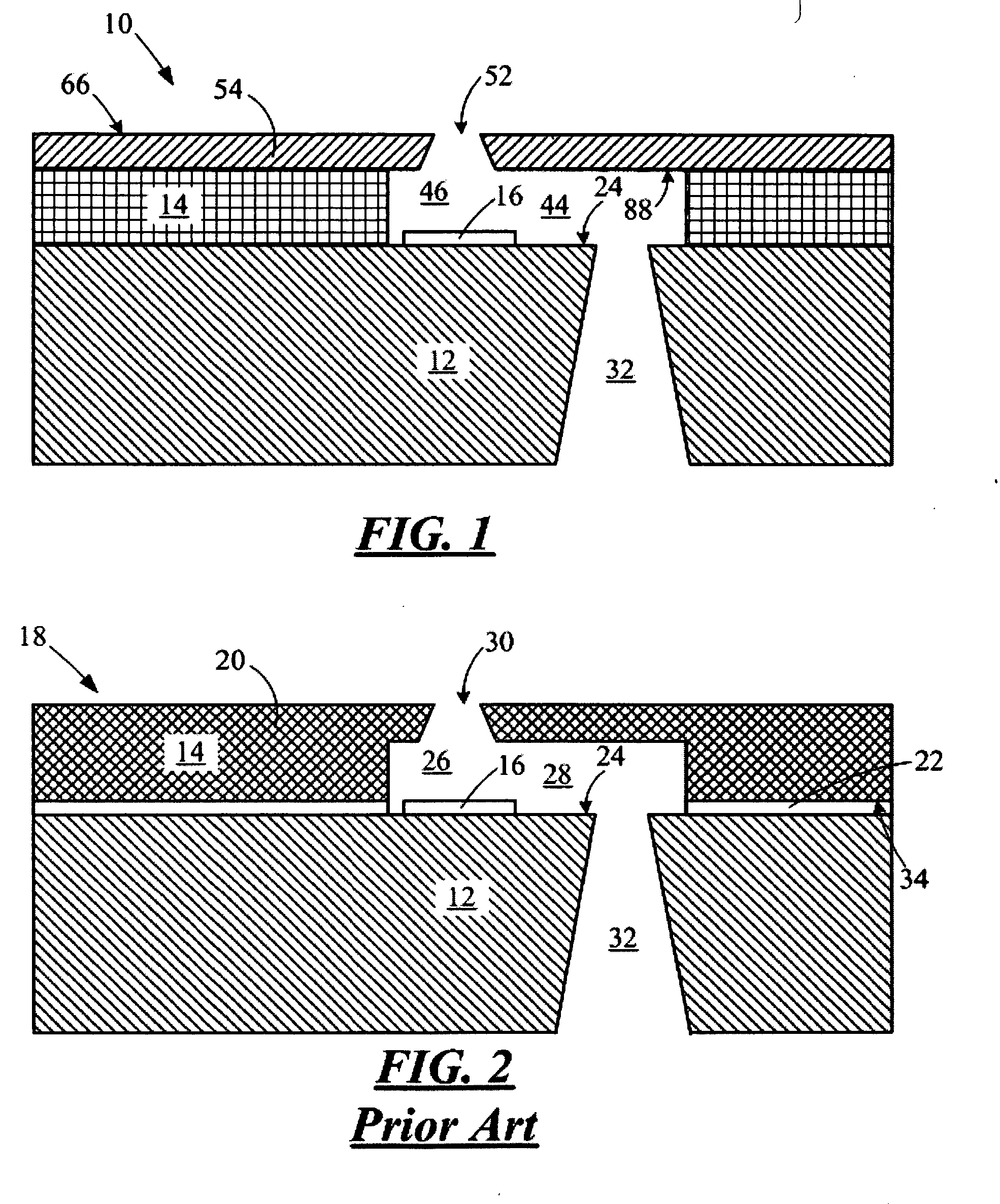
[0024] With reference to FIG. 1, there is shown, in partial cross-sectional view, a portion of a micro-fluid ejection head 10. The micro-fluid ejection head 10 includes a thick film layer 14 attached to a substrate, such as semiconductor substrate 12 having various insulative, conductive, resistive, and passivating layers providing a fluid ejector actuator 16.

[0025]FIG. 2 depicts a prior art micro-fluid ejection head 18, wherein a nozzle member, such as nozzle plate 20, is attached as by an adhesive 22 to a device surface 24 of the semiconductor substrate 12. In such a micro-fluid ejection head 18, the nozzle plate 20 is made out of a laser ablated material such as polyimide. The polyimide material is laser ablated to provide a fluid chamber 26 in fluid flow communication with a fluid supply channel 28. Upon activation of the ejector actuator 16, fluid is expelled through a nozzle 30 that is also laser ablated in the polyimide material of the nozzle plate 20. The fluid chamber 26 a...


PUM


Abstract

Improved photoimaged nozzle members for a micro-fluid ejection head, micro-fluid ejection heads containing such nozzle members, and methods for making any of the same. One such nozzle member is provided by a photoresist nozzle layer applied adjacent a thick film layer on a substrate having fluid ejector actuators. The photoresist nozzle layer has a plurality of nozzles therein. The nozzles are formed in the nozzle layer from an exit surface of the nozzle layer to an entrance surface of the nozzle layer. The nozzles have a reentrant hole profile with a wall angle greater than about 40 up to about 30° measured from an axis orthogonal to a plane defined by the exit surface of the nozzle layer.

Description

FIELD [0001] The disclosure relates to improved nozzle members for micro-fluid ejection heads, and in particular embodiments to methods and compositions for forming reentrant nozzles in photoimageable materials. BACKGROUND AND SUMMARY [0002] Micro-fluid ejection devices, such as ink jet printers continue to evolve as the technology for ink jet printing continues to improve to provide higher speed, higher quality printers. However, the improvement in speed and quality does not come without a price. The micro-fluid ejection heads are more costly to manufacture because of tighter alignment tolerances. [0003] For example, some conventional micro-fluid ejection heads are made with nozzle members (e.g., nozzle plates) containing flow features. The nozzle plates are then aligned and adhesively attached to a semiconductor substrate. However, minor imperfections in the substrate or nozzle plate components of the ejection head or improper alignment of the parts has a significant impact on the...

Claims


Application Information

Patent Timeline
IPC IPC(8): B41J2/14B41J2/16G01D15/00G11B5/127
CPCB41J2/1603B41J2/162B41J2/1631B41J2/1645
Inventor HART, BRIAN C.HOLT, GARY A. JR.WALDECK, MELISSA M.WEAVER, SEAN T.WILLIAMS, GARY R.
Owner SLINGSHOT PRINTING LLC
Why Eureka
Try Eureka