Projection optical system inspecting method and inspection apparatus, and a projection optical system manufacturing method

a technology of projection optical system and inspection method, which is applied in the direction of optical apparatus testing, printing, instruments, etc., can solve the problems of increasing the cost of the projection optical system itself, reducing the degree of freedom in the design etc., and achieves accurate inspection, accurate inspection, and easy inspection of the projection optical system

Inactive Publication Date: 2007-04-05
NIKON CORP
View PDF99 Cites 36 Cited by
  • Summary
  • Abstract
  • Description
  • Claims
  • Application Information

AI Technical Summary

Benefits of technology

[0019] According to the present invention, the optical performance of an immersion projection optical system can be accurately inspected because, when inspecting the optical performance of the projection optical system, which is the object to be inspected, a liquid is supplied on the image plane side of the projection optical system, and the measuring beam that passes through the projection optical system and the liquid is photoelectrically detected. In addition, because the inspection is performed in a state wherein liquid is filled between the projection optical system and the flat surface part of the optical member, or between the projection optical system and the flat part and the reflecting spherical surface part, the wavefront of the measuring beam is not disturbed by the convection of the liquid, the liquid absorbs little of the measuring beam, and the optical performance of a liquid immersion type projection optical system can be accurately inspected.
[0020] In addition, because the liquid is supplied between the projection optical system and the flat surface part of the optical member, or between the projection optical system and the flat part and the reflecting spherical surface part, the optical member and the reflecting spherical surface part can be moved easily, and the inspection of the projection optical system can be performed easily.

Problems solved by technology

Because shortening the wavelength of the illumination light restricts the glass material that can be used for the lens of the projection optical system, the degrees of freedom in the design of the projection optical system unfortunately decrease, and the cost of the projection optical system itself unfortunately increases.

Method used


Image

  • Projection optical system inspecting method and inspection apparatus, and a projection optical system manufacturing method
  • Projection optical system inspecting method and inspection apparatus, and a projection optical system manufacturing method
  • Projection optical system inspecting method and inspection apparatus, and a projection optical system manufacturing method

Examples


first embodiment

(First Embodiment)

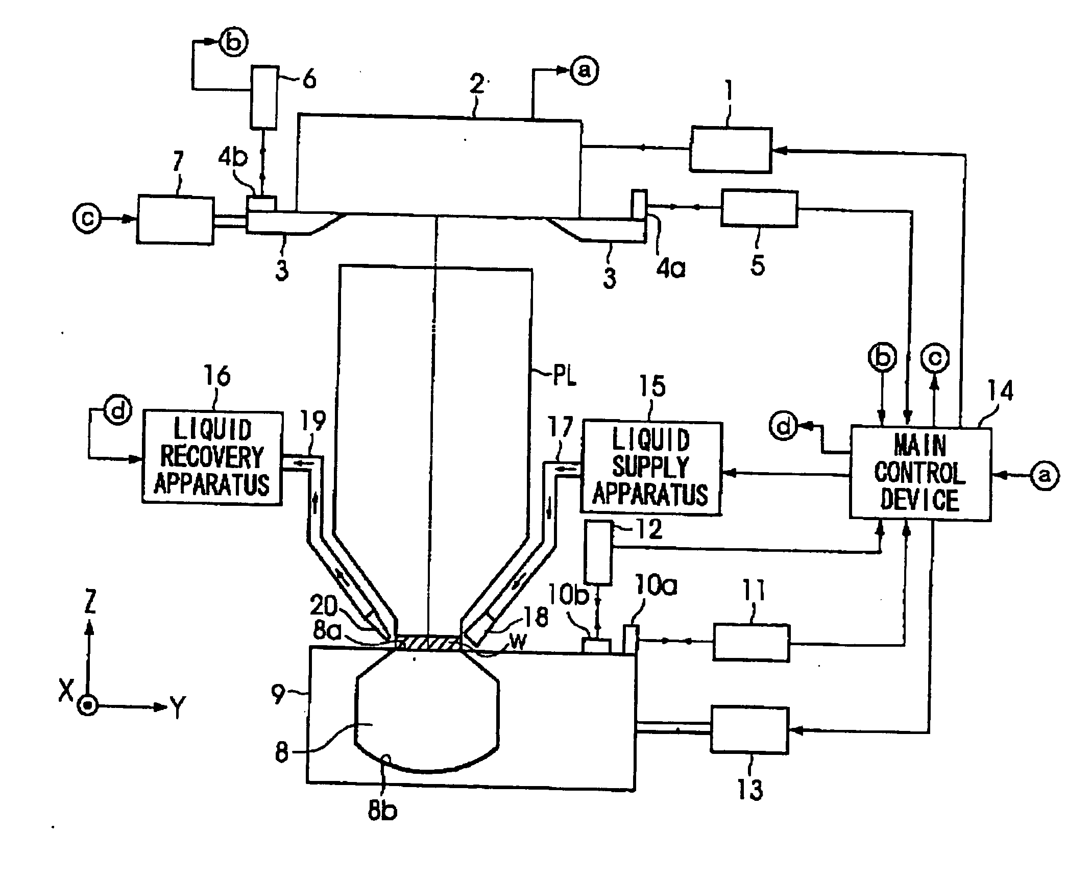
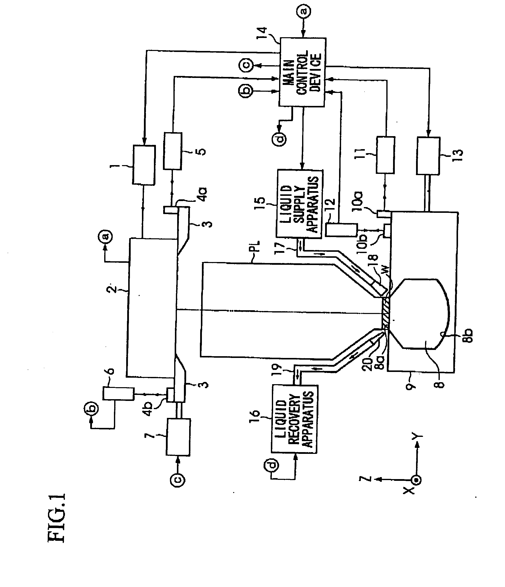
[0032]FIG. 1 is a schematic view of the overall constitution of the inspection apparatus according to one embodiment of the present invention. Furthermore, in the following explanation, the figure is based on an XYZ orthogonal coordinate system, and the explanation of the positional relationships of each member is made referencing this XYZ orthogonal coordinate system. The XYZ orthogonal coordinate system is set so that the Y axis and the Z axis are parallel to the paper surface, and the X axis is in a direction orthogonal to the paper surface. The XYZ coordinate system in the figure is set so that the XY plane is actually parallel to a horizontal plane, and the Z axis is set to the vertically upward direction.

[0033] In FIG. 1, reference numeral 1 is a light source that emits a light beam with a cross section having a prescribed shape, e.g., an ArF excimer laser light source (193 nm wavelength). The light beam emitted from the light source 1 is supplied to an inte...

second embodiment

(Second Embodiment)

[0065] The following explains the second embodiment of the present invention. The inspection apparatus according to the second embodiment of the present invention is constituted substantially the same as the inspection apparatus depicted in FIG. 1, but differs in that, instead of the folding glass member 8, a folding glass member 32 and a holder 31, depicted in FIG. 3, are disposed on the stage 9. FIG. 3A and FIG. 3B depict the constitution of the folding glass member 32 provided in the inspection apparatus according to the second embodiment of the present invention; FIG. 3A is a cross sectional view of the folding glass member 32, and FIG. 3B is a top oblique view of the folding glass member 32.

[0066] The folding glass member 32, like the folding glass member 8, reflects the measuring beam that passed through the projection optical system PL and the liquid w, and again guide it to the projection optical system PL. The folding glass member 32 is a semispherical s...

fourth embodiment

(Fourth Embodiment)

[0082] The following explains the fourth embodiment of the present invention. The inspection apparatus according to the fourth embodiment of the present invention is constituted substantially the same as the inspection apparatus depicted in FIG. 3, but differs in that, instead of the holder 33 provided on the stage 9 and wherein the reflecting spherical surface part 34 is formed, a holder 35 is provided wherein a plurality of reflecting spherical surface parts 36 are formed. FIG. 5A and FIG. 5B depict the constitution of the reflecting spherical surface parts 36 and the holder 35 provided in the inspection apparatus according to the fourth embodiment of the present invention; FIG. 5A is a cross sectional view of the reflecting spherical surface parts 36 and the holder 35, and FIG. 5B is a top oblique view of the reflecting spherical surface parts 36 and the holder 35.

[0083] The holder 35 is a flat shaped plate made of, for example, aluminum (Al). A plurality of r...


PUM

PropertyMeasurementUnit
wavelengthaaaaaaaaaa
temperatureaaaaaaaaaa

Abstract

In the inspection apparatus of this projection optical system, a folding glass member, comprising a flat surface part and a reflecting spherical surface part opposing to the flat surface part, is disposed on the image plane side of the projection optical system so that the flat surface part opposes to the projection optical system. Further, in a state wherein a liquid is supplied between the projection optical system and the folding glass member, a measuring beam emitted from an interferometer unit enters the projection optical system; the measuring beam that transmitted through the projection optical system and the liquid, and entered the folding glass member is reflected by the reflecting spherical surface part, and once again passes through the liquid and the projection optical system; and the interference fringes obtained from the measuring beam and the reference beam generated within the interferometer unit are detected.

Description

CROSS-REFERENCE TO RELATED APPLICATION [0001] This is a Divisional of U.S. patent application Ser. No. 11 / 335,461 filed Jan. 20, 2006, which in turn is a Continuation of International Application No. PCT / JP2004 / 010863 filed Jul. 23, 2004, which claims priority to Japanese Patent Application No. 2003-279929, filed Jul. 25, 2003. The disclosures of each of the aforementioned applications are incorporated herein by reference in their entireties.BACKGROUND OF THE INVENTION [0002] 1. Field of the Invention [0003] The present invention relates to a projection optical system inspecting method and inspection apparatus, and a projection optical system manufacturing method, and more particularly relates to a projection optical system inspecting method and inspection apparatus, and a projection optical system manufacturing method, wherein the projection optical system is provided with an exposure apparatus, used in a lithographic process, that projects an image of a pattern formed on a mask on...

Claims


Application Information

Patent Timeline
Patent Type & Authority Applications(United States)
IPC IPC(8): G03B27/42G01M11/02G03F7/20
CPCG01M11/0214G01M11/0257G01M11/0271G03F7/70341G03F7/706
Inventor ISHII, MIKIHIKOICHIHARA, YUTAKAGEMMA, TAKASHI
Owner NIKON CORP
Why Eureka
Try Eureka