Liquid crystal display, illuminant module and its manufacturing method

a technology of illuminant modules and liquid crystal displays, which is applied in the field of illuminant modules, can solve the problems of deteriorating the performance of leds themselves and peripheral devices, adversely affecting the long-term reliability of illuminant modules, and different magnitudes of thermal expansion, so as to achieve high optical extraction efficiency, high image quality, and high cooling efficiency

Inactive Publication Date: 2007-04-05
HITACHI LIGHTING
View PDF6 Cites 49 Cited by
  • Summary
  • Abstract
  • Description
  • Claims
  • Application Information

AI Technical Summary

Benefits of technology

[0009] The present invention makes it possible to construct a long illuminant module. Consequently, a liquid crystal display device enjoying high image quality without suffering from luminance lines can be provided. Moreover, a liquid crystal display device featuring high optical extraction efficiency, high cooling efficiency, low power consumption, and high reliability can be realized.

Problems solved by technology

A rise in temperature derived from the heat dissipation deteriorates the performances of the LEDs themselves and peripheral devices respectively and adversely affects the long-term reliability of an illuminant module.
Therefore, the rise in temperature occurring when the LEDs perform self-heating causes a difference in a magnitude of thermal expansion on an interface between the encapsulating resin and metal substrate that are bonded to each other.
This may lead to bending or interfacial debonding of the bonded interface.
However, when a transparent encapsulating resin and the metal substrate are bonded to have a wide interface, a large thermal stress may be applied to each of the encapsulating resin and metal substrate.
This may cause debonding of the bonded interface between the encapsulating resin and metal substrate or bending.
Eventually, homogeneous planar illumination may not be attained.

Method used


Image

  • Liquid crystal display, illuminant module and its manufacturing method
  • Liquid crystal display, illuminant module and its manufacturing method
  • Liquid crystal display, illuminant module and its manufacturing method

Examples


first embodiment

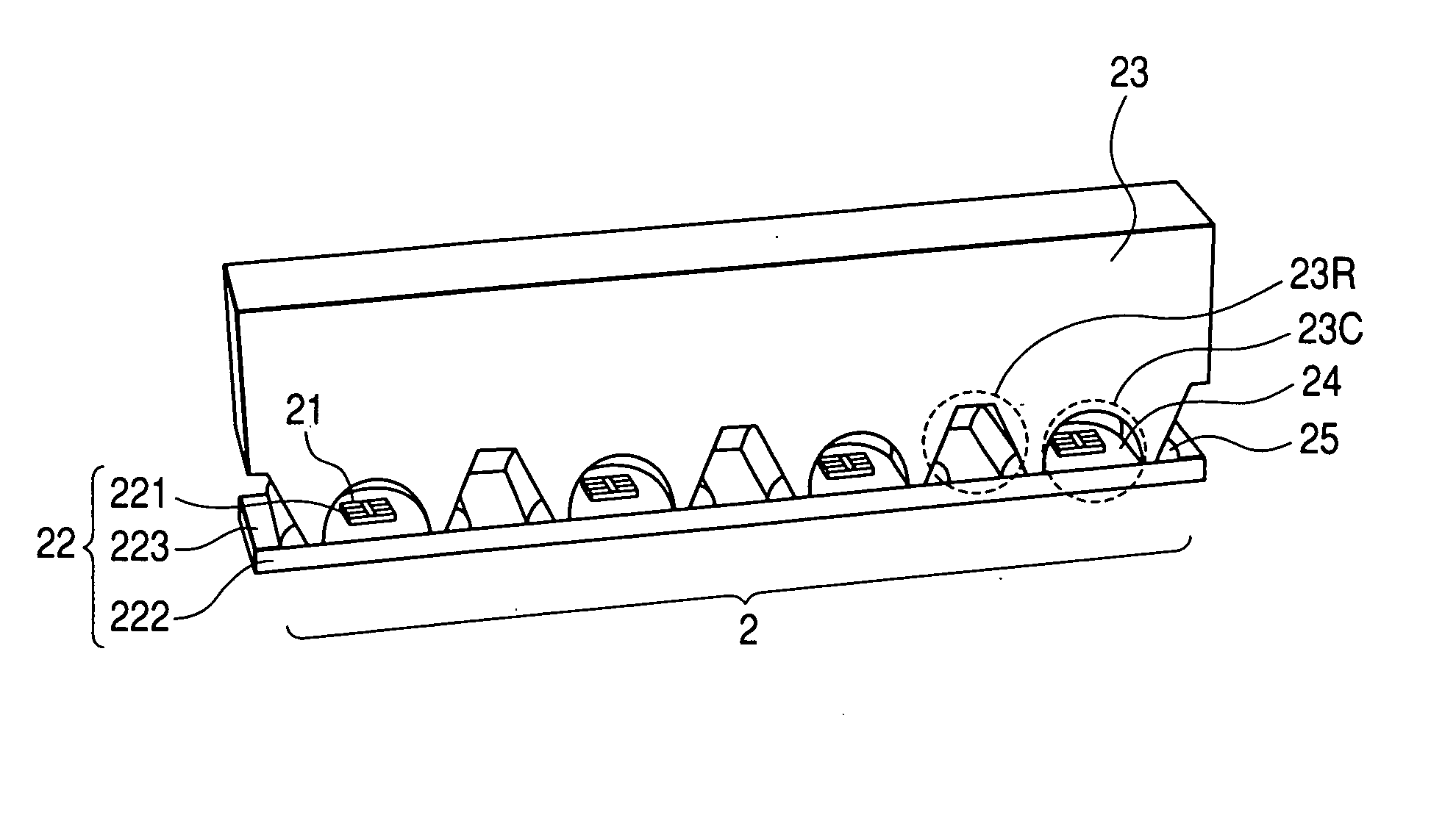
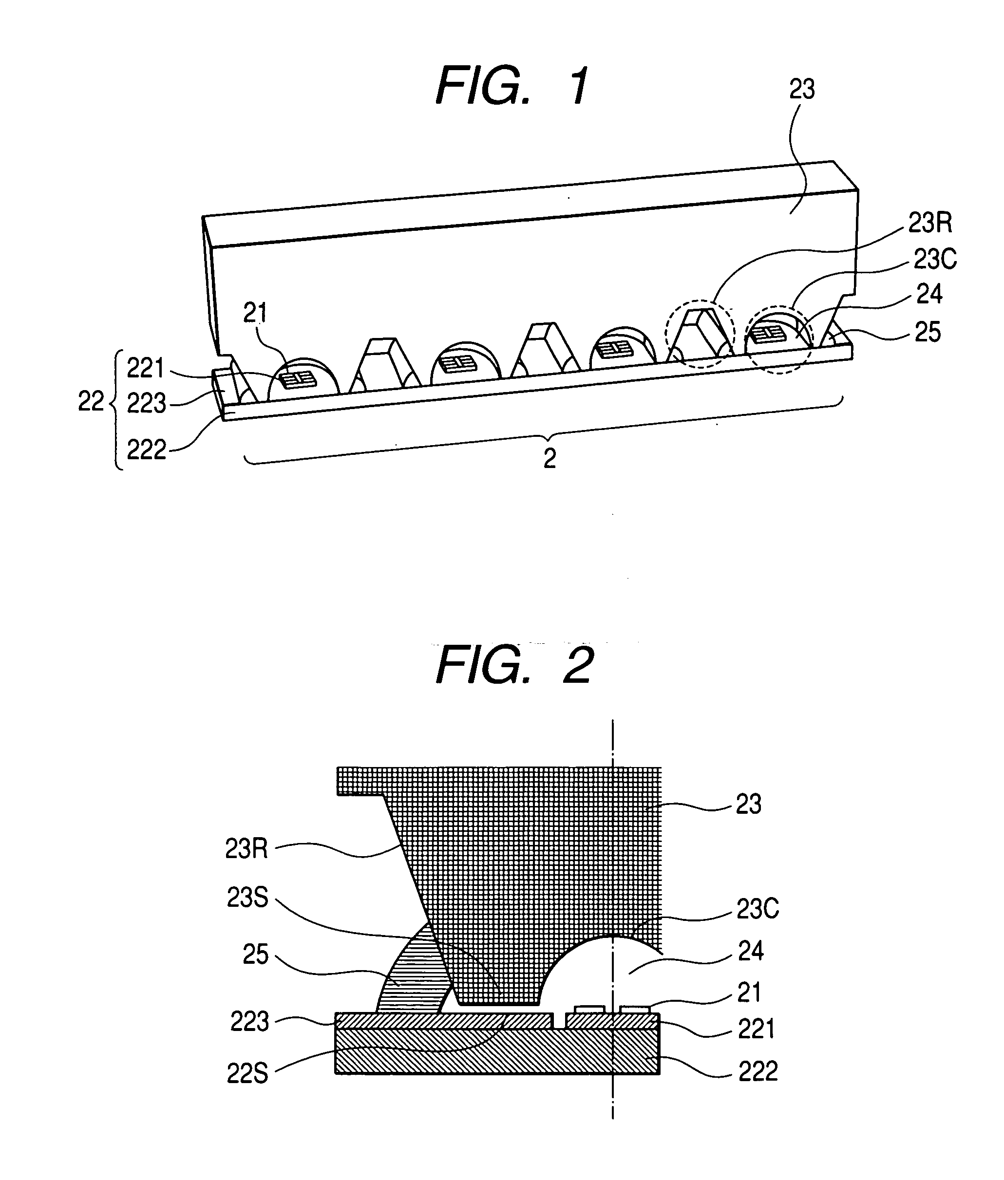
[0017]FIG. 1 is a perspective view showing the structure of the first embodiment of an illuminant module in accordance with the present invention. FIG. 2 is a longitudinal cross-sectional view of a bonding material included in the illuminant module and its surroundings. In the drawings, there are shown an illuminant module 2, light emitting elements 21, a substrate 22 (sub-mounts 221, a metal substrate 222, a printed-circuit board 223), a lens material 23 (cavities 23C and notches 23R), a transparent encapsulating resin 24, and a coupling member 25.

[0018] The illuminant module 2 includes the light emitting elements 21, the sub-mounts 221 on which the light emitting elements are mounted, the metal substrate 222 on which the plurality of sub-mounts 221 is mounted, the transparent encapsulating resin 24 which encapsulates the sub-mounts 221 and light emitting elements 21 on the metal substrate 222, the lens material 23 that covers the metal substrate 222 and transparent encapsulating ...

second embodiment

[0023] The second embodiment has the same constituent features as the first embodiment. In addition, the Young's modulus of the transparent encapsulating resin 24 and bonding material 25 respectively are lower than the Young's modulus of the lens material 23. Owing to this constituent feature, the bonding material 25 can more greatly deform than it does in the first embodiment. Moreover, when the Young's modulus of the transparent encapsulating resin 24 is lower than that of the lens material 23, the entire interface between the lens material 23 and substrate 22 can deform greatly. Consequently, even if relative positioning errors derived from a difference in a magnitude of thermal deformation between the lens material 23 and substrate 22 get large, the relative positioning errors can be absorbed. A thermal stress working on the interface between the lens material 23 and substrate 22 can be alleviated. Therefore, interfacial debonding of the bonded part between the lens material 23 ...

third embodiment

[0024] As the third embodiment, an embodiment of a liquid crystal display device including the illuminant module in accordance with the first or second embodiment of the present invention will be described in conjunction with drawings.

[0025]FIG. 4 is a perspective view showing the structure of an embodiment of a liquid crystal display device in accordance with the present invention. In the drawing, there are shown a liquid crystal display device 1, an illuminant module 2, a light guide plate 3, a reflection sheet 4, an optical sheet 5, a liquid crystal panel 6, and a heat sink 7. The reflection sheet 4 includes a back reflection sheet 41 that covers the entire back of the light guide plate 3, and a lateral reflection sheet 42 that reflects light leaking out of the illuminant module 2. The optical sheet 5 includes lengthwise and sideways prism sheets 51 and 52, and a diffusion sheet 53.

[0026] The light emitting elements 21 emit light through the light emitting surface of the lens m...


PUM

PropertyMeasurementUnit
transparentaaaaaaaaaa
Young's modulusaaaaaaaaaa
adhesionaaaaaaaaaa

Abstract

When a long illuminant module is constructed, debonding of a bonded interface or bending occurs due to a difference in a magnitude of thermal deformation between a lens material and a metal substrate. In an illuminant module including light emitting elements, a substrate on which the light emitting elements are mounted, a transparent encapsulating resin which encapsulates the light emitting elements, and a lens material having cavities formed therein, in which the respective light emitting elements and transparent encapsulating resin are stored, notches are formed in a surface of the lens material on the side of the substrate, and the notch surfaces of the notches and the surface of the substrate are bonded using a bonding material.

Description

CLAIM OF PRIORITY [0001] The present application claims priority from Japanese Application JP 2005-281063 filed on Sep. 28, 2005, the content of which is hereby incorporated by reference into this application. BACKGROUND OF THE INVENTION [0002] 1. Field of the Invention [0003] The present invention relates to an illuminant module and a method of preparing a liquid crystal display device and the illuminant module. More particularly, the present invention is concerned with a backlight that uses a light guide plate to illuminate a liquid crystal panel from the back of the liquid crystal panel. [0004] 2. Description of the Related Art [0005] At present, light-emitting diodes (LEDs) provide only a lower luminous efficacy than a cold-cathode fluorescent lamp. Therefore, the LEDs are mounted at a high density, and a large current is fed to the LEDs in order to increase a luminous quantity. Moreover, the use efficiency of light is improved in order to draw out a luminance level equal to a l...

Claims


Application Information

Patent Timeline
Patent Type & Authority Applications(United States)
IPC IPC(8): F21V7/04H01J1/62F21S2/00F21Y101/02G02F1/13357H01L33/00H01L33/58
CPCG02B6/0021G02B6/0028
Inventor KINOSHITA, YASUSHINAKAZATO, NORIOYOTSUMOTO, NAOKINISHIMURA, KEISUKENAKAHARA, DAISUKE
Owner HITACHI LIGHTING
Why Eureka
Try Eureka