Eureka AIR delivers breakthrough ideas for toughest innovation challenges, trusted by R&D personnel around the world.

System for measuring atmospheric turbulence

a technology of atmospheric turbulence and system, which is applied in the direction of ict adaptation, reradiation, instruments, etc., can solve the problems of inability to use temperature probes in many situations, limited to weak scintillation regimes, and limited resources, so as to improve the performance of adaptive optics and accurate estimates

Inactive Publication Date: 2007-04-05
TREX ENTERPRISES CORP
View PDF4 Cites 43 Cited by
  • Summary
  • Abstract
  • Description
  • Claims
  • Application Information

AI Technical Summary

Benefits of technology

"The present invention provides equipment and techniques for accurately estimating the turbulence profile to improve the performance of adaptive optics systems designed to compensate the degradation effects of turbulence on directed energy systems, in astronomy, and in laser communication systems. The invention includes a cross-path LIDAR, which uses laser guide star technology combined with a cross-path wavefront sensing method. The cross-correlation coefficients of the wavefront slope are calculated, and the turbulence profile of refractive index structure characteristic Cn2(z) is reconstructed from the measured slope cross-correlations. The invention has validated the feasibility of the cross-path LIDAR technique and performed various tasks such as sensitivity analysis, inversion algorithm development, and evaluation of the optimal spectral waveband and imaging camera for field demonstration. The invention can measure three atmospheric characteristics: turbulence profile, turbulence outer scale, and wind velocity, which are useful for calculating wave propagation parameters."

Problems solved by technology

In particular: in-situ measurements using temperature probes are not possible in many situations DIM sensor provides only path-integrated information.
It is limited to weak scintillation regimes.
It requires and is limited by availability of bright binary stars.
Consequently, it has limited temporal resolution.
It does not allow us to measure turbulence from a moving platform.

Method used


Image

  • System for measuring atmospheric turbulence
  • System for measuring atmospheric turbulence
  • System for measuring atmospheric turbulence

Examples


Embodiment Construction

Cross-Path LIDAR Concept

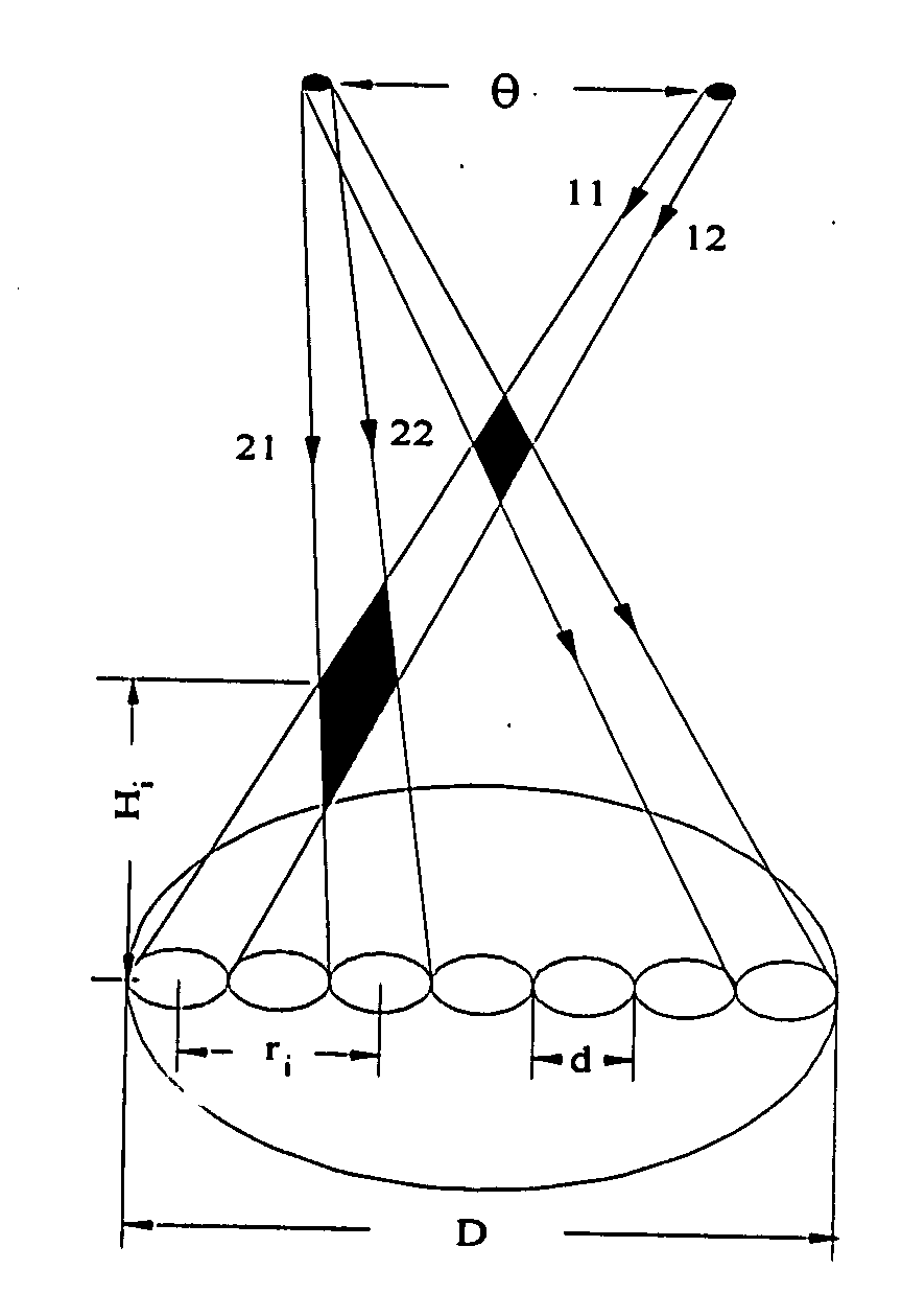
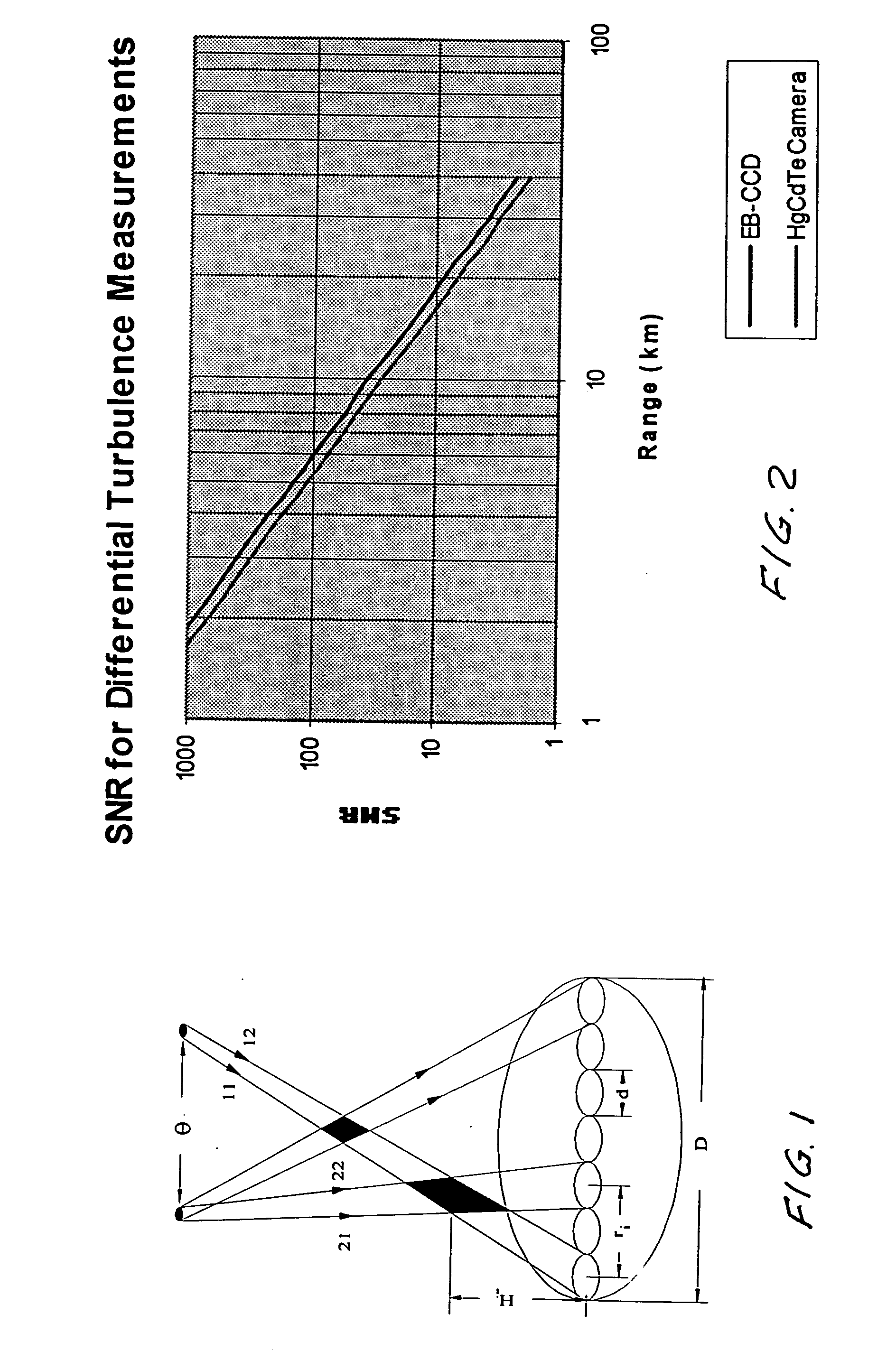
[0050] The cross-path LIDAR uses two laser guide stars (LGSs) separated at angular distance θ that are created at the fixed measurement range using a pulsed laser. The wavefront slopes of a laser return from each LGS are measured with a Hartmann wavefront sensor having nsub=D / Dsub sub-apertures, where D is the telescope aperture diameter, Dsub is the sub-aperture diameter.

[0051] The physical principal of the cross-path LIDAR is the following. For a binary LGS with angular separation θ a single turbulent layer at altitude H produces two “copies” of the aberrated wavefront in the pupil plane of the telescope, shifted by distance S=Hθ with respect to one another. Hence, the cross-correlation of the wavefront slopes has a peak at baseline separation S in the direction of the binary separation. Consequently, the cross-correlation of the wavefront slope at the separation S is sensitive to the strength of turbulence of the turbulent layer located at the altitude H...


PUM


Abstract

Equipment and techniques for the accurate estimates of the turbulence profile to improve the performance of adaptive optics systems designed to compensate the degradation effects of turbulence on directed energy systems, in astronomy, and in laser communication systems. The present invention is an optical turbulence profiler. The invention includes a cross-path LIDAR. The cross-path LIDAR technique uses laser guide star technology combined with a cross-path wavefront sensing method. In this method, two Rayleigh, or sodium, laser beacons separated at some angular distance are created by using a pulsed laser and a range-gated receiver. In preferred embodiments a Hartmann wavefront sensor measures the wavefront slopes from two laser guide stars. The cross-correlation coefficients of the wavefront slope are calculated, and the turbulence profile of refractive index structure characteristic Cn2(z) is reconstructed from the measured slope cross-correlations.

Description

[0001] This application claims the benefit of Provisional Application Ser. No. 60 / 722,749.[0002] The present invention relates to systems for measuring atmospheric turbulence. This invention was made in the course of the performance of Contract No. FA9450-05-M-0064 with United States Air Force Research Laboratory and the United States Government has rights in the invention.BACKGROUND OF THE INVENTION [0003] Random variations of the index of refraction called refractive degrade laser beams that propagate through the atmosphere including high-energy laser (HEL) beams. High bandwidth tracking and adaptive optics (AO) systems can compensate for the effects of turbulence. However, in order to understand the results of the laser propagation tests with AO systems, knowledge of the distribution of the strength of turbulence along the propagation path is required. A required optical sensor must have high spatial and temporal resolution, be independent of availability of stars, be able to ope...

Claims


Application Information

Patent Timeline
Patent Type & Authority Applications(United States)
IPC IPC(8): H04B10/00
CPCG01S17/023G01S17/95G01S17/86Y02A90/10
Inventor BELENKIY, MIKHAIL
Owner TREX ENTERPRISES CORP
Why Eureka
Eureka Blog
Learn More