Melt redistribution element for an injection molding apparatus

a technology of redistribution element and injection molding apparatus, which is applied in the field of redistribution element, can solve the problems of unavoidable flow imbalance, temperature imbalance between material along the side of the channel, adjustment or local correction, etc., and achieves the effect of reducing the diameter of the manifold, improving homogenization, and not invasiv

Active Publication Date: 2007-04-05
MOLD MASTERS 2007
View PDF44 Cites 25 Cited by
  • Summary
  • Abstract
  • Description
  • Claims
  • Application Information

AI Technical Summary

Benefits of technology

[0019] According to another embodiment of the invention, the melt redistributing method includes providing a melt redistribution element that: a) provides a non-invasive local pressure increase of the melt by reducing the diameter of the manifold melt channel at the inlet and b) provides a non-invasive melt splitting and redirection of the melt stream by allowing a central portion of the pressurized melt to continue to follow a straight pathway and forcing an outer portion of the melt stream to follow a helical melt pathway. A certain degree of mixing between the central portion of the melt stream and the outer portion of the melt stream may occur while the melt flows through the melt redistribution element. The degree of mixing depends of various factors and variables such as the level, or the amount, of the pressure increase, the length of the melt redistribution element's melt bore and the helical melt pathway, the pitch or the density of the helical pathway and the viscosity and the temperature of the melt. More mixing and better homogenizing is achieved with some molten materials when the melt redistribution element has more than one helical melt pathway.

Problems solved by technology

This flow imbalance is unavoidable and is characterized by a variable, non-symmetrical, cross-sectional distribution (or profile) of the temperature, viscosity and velocity of the melt along each melt channel of the manifold.
Since material along the sides of the channel moves more slowly than material in the center, it is exposed to the heat from the manifold for a longer period of time than the faster, more centrally-disposed material causing a temperature imbalance between material in the middle of a channel and material along the sides of a channel.
Since it is very difficult to adjust or locally correct the temperature and pressure differences to a particular channel in a multi-channel injection molding apparatus, variations in shear stress profiles lead to inconsistent molded products from one mold cavity to another and from one batch of molded products to the next.
Further, side-to-side (or uneven or non-symmetrical) shear stress and temperature cross-sectional profiles may cause different flow characteristics from one side to the other of a single molded product, causing poor quality parts to be produced.
However, these attempts generally require splitting the melt stream via a mechanical obstruction, which may lead to flow lines, particularly with materials that are sensitive to the development of flow lines.

Method used


Image

  • Melt redistribution element for an injection molding apparatus
  • Melt redistribution element for an injection molding apparatus
  • Melt redistribution element for an injection molding apparatus

Examples


Embodiment Construction

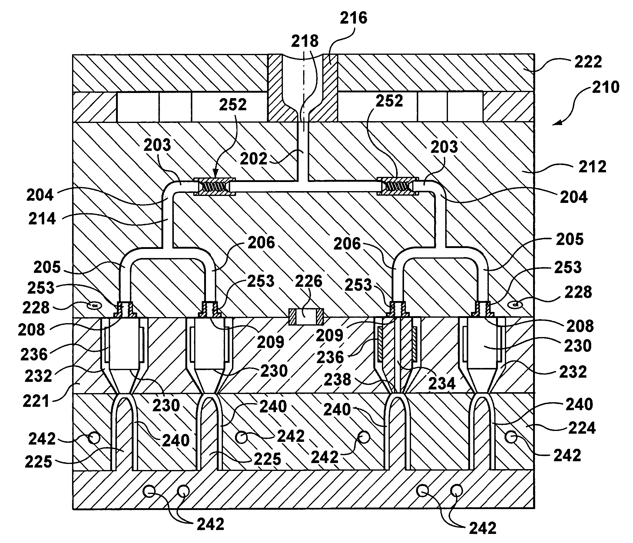
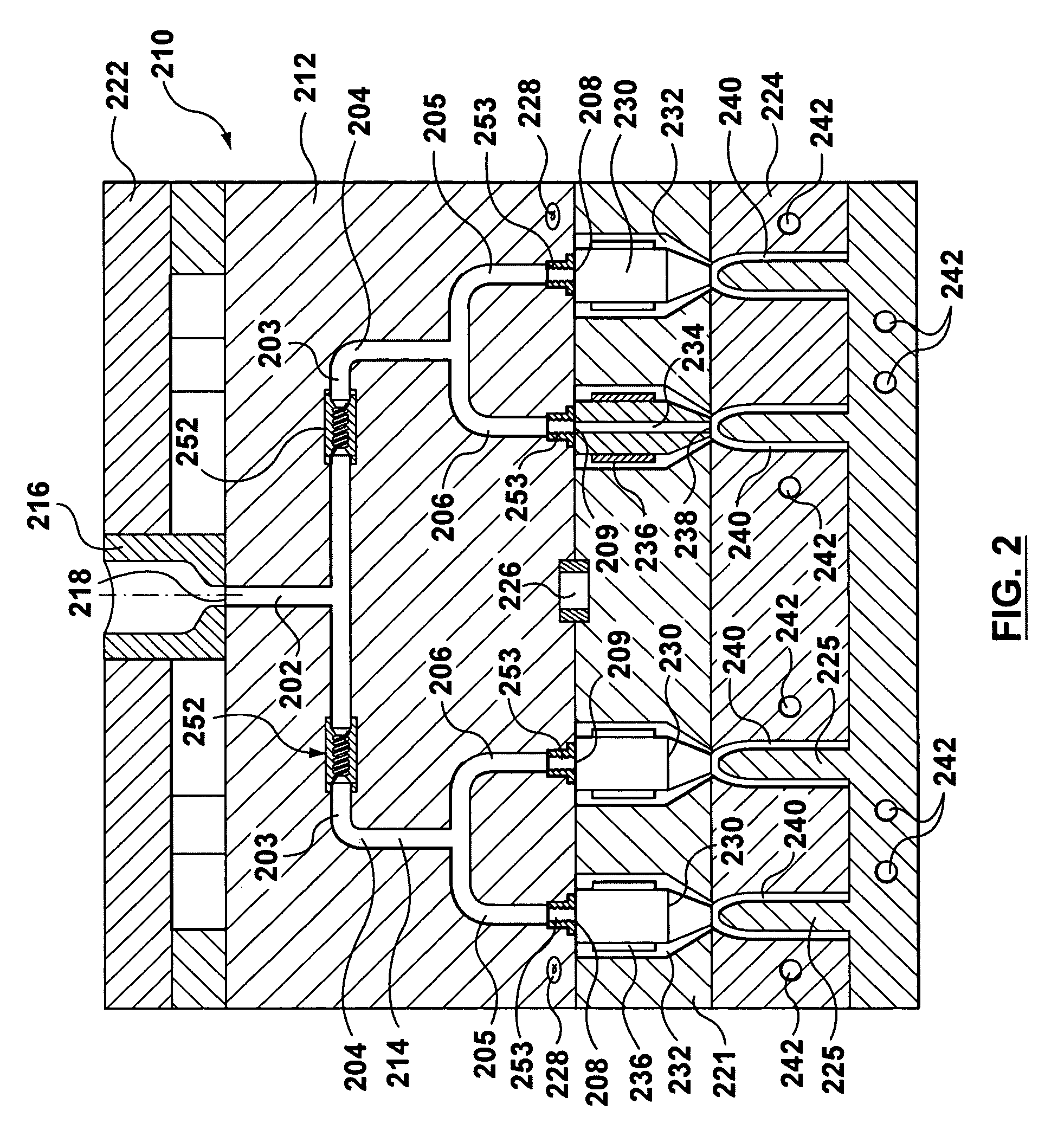
[0032] Referring now to FIG. 2, an injection molding apparatus according to an embodiment of the invention is generally shown at 210. Injection molding apparatus 210 includes a two level manifold 212 having manifold channels 214. As shown, manifold channels 214 are in communication with an inlet melt channel 202 that splits into at least two melt branches 203 downstream of a manifold inlet 218. Melt from channel 202 enters a melt redistribution element 252 within each branch 203. Melt redistribution element 252 will be discussed in further detail below, with respect to melt redistribution element 352 of FIG. 3. Each branch 203 turns a corner 204 and splits again into branches 205 and 206. Manifold 212 is spaced between a mold block back plate 222 and a cavity mold plate 224. Manifold 212 is located relative to the cavity mold plate 224 by a locating ring 226. A sprue bushing 216 is coupled to the manifold inlet 218. The sprue bushing 216 receives melt from a machine nozzle (not show...


PUM

PropertyMeasurementUnit
pressureaaaaaaaaaa
diameteraaaaaaaaaa
temperatureaaaaaaaaaa

Abstract

An injection molding apparatus having a manifold and several manifold melt channels communicating with several hot runner nozzles includes a melt redistribution element. The melt redistribution element is placed at specific locations along the melt channels to balance the uneven shear stress profile accumulated during the flow of a melt along the manifold channels. The melt redistribution element has an unobstructed central melt bore having at its inlet a narrowing tapered channel portion. The melt redistribution element also includes a helical melt pathway portion that surrounds the central melt bore. The incoming melt is first subjected to a pressure increase by the tapered portion that causes the melt to flow at a higher velocity through the central melt bore. The outer portion of the melt is forced to flow along the helical path and thus it changes direction multiple times and partially mixes with the melt flowing through the central melt bore. Accordingly, at the outlet of the melt redistribution element the shear stress profile is more evenly distributed than at the inlet of the redistribution element.

Description

FIELD OF THE INVENTION [0001] The present invention relates generally to a melt redistribution element and method to improve the homogeneity of melt material in an injection molding hot runner apparatus. BACKGROUND OF THE INVENTION [0002] In a conventional injection molding apparatus, melt material is delivered from an injection molding machine and flows through a hot runner manifold generally having a plurality of circular cross-section manifold channels. The manifold has an inlet and a plurality of outlets communicating with a plurality of hot runner nozzles and is heated to maintain the melt at a consistent and flowable temperature. Several variables affect the quality of the molded parts produced using hot runner manifolds. One such variable is the shear stress-induced flow imbalance that can be observed or measured along the melt channels and at the outlets of the manifold. This flow imbalance is unavoidable and is characterized by a variable, non-symmetrical, cross-sectional d...

Claims


Application Information

Patent Timeline
Patent Type & Authority Applications(United States)
IPC IPC(8): B29C47/36
CPCB01F5/0646B01F5/0652B01F5/0655B01F2005/0017B29B7/325B29C45/30B29C2045/308B01F2025/913B01F25/4335B01F25/4338B01F25/433
Inventor OLARU, GHEORGHEGOSLINSKI, RHONDA
Owner MOLD MASTERS 2007
Why Eureka
Try Eureka