
System and method for adapting system parameters in radio based communications systems

a radio based communication and system parameter technology, applied in the field of radio based communication systems, can solve the problem of fast adaptation and the lik

Active Publication Date: 2007-04-05
ALCATEL LUCENT SAS
View PDF4 Cites 8 Cited by
  • Summary
  • Abstract
  • Description
  • Claims
  • Application Information

AI Technical Summary

Benefits of technology

[0015] Advantageously, the relative velocity of the transmitter unit and the receiver unit can be determined without requiring any additional measuring signal by using the (relativistic) Doppler effect which leads to a frequency shift of the radio spectrum used by the entities. Therefore, in a further embodiment of the method according to the present invention, a Doppler frequency shift Δf of a radio frequency signal transmitted between the transmitter unit and the receiver unit, in particular of at least parts of a radio frequency spectrum used for communication by the radio based communications system, is measured to determine a relative velocity of the transmitter unit and the receiver unit, e.g.: Δ⁢ ⁢f=f-f0=f0·[(1+vR / c)1-vR2 / c2-1]≈f0·vRc,(1)
[0019] Alternatively, a narrowband or single-frequency pilot signal may be employed to improve the accuracy of the Doppler shift measurement process. In a corresponding embodiment of the method according to the invention the distance between the transmitter unit and the receiver unit is determined by measuring a propagation time of a dedicated pilot signal transmitted between the transmitter unit and the receiver unit. To this end, the method according the present invention advantageously comprises the following steps:
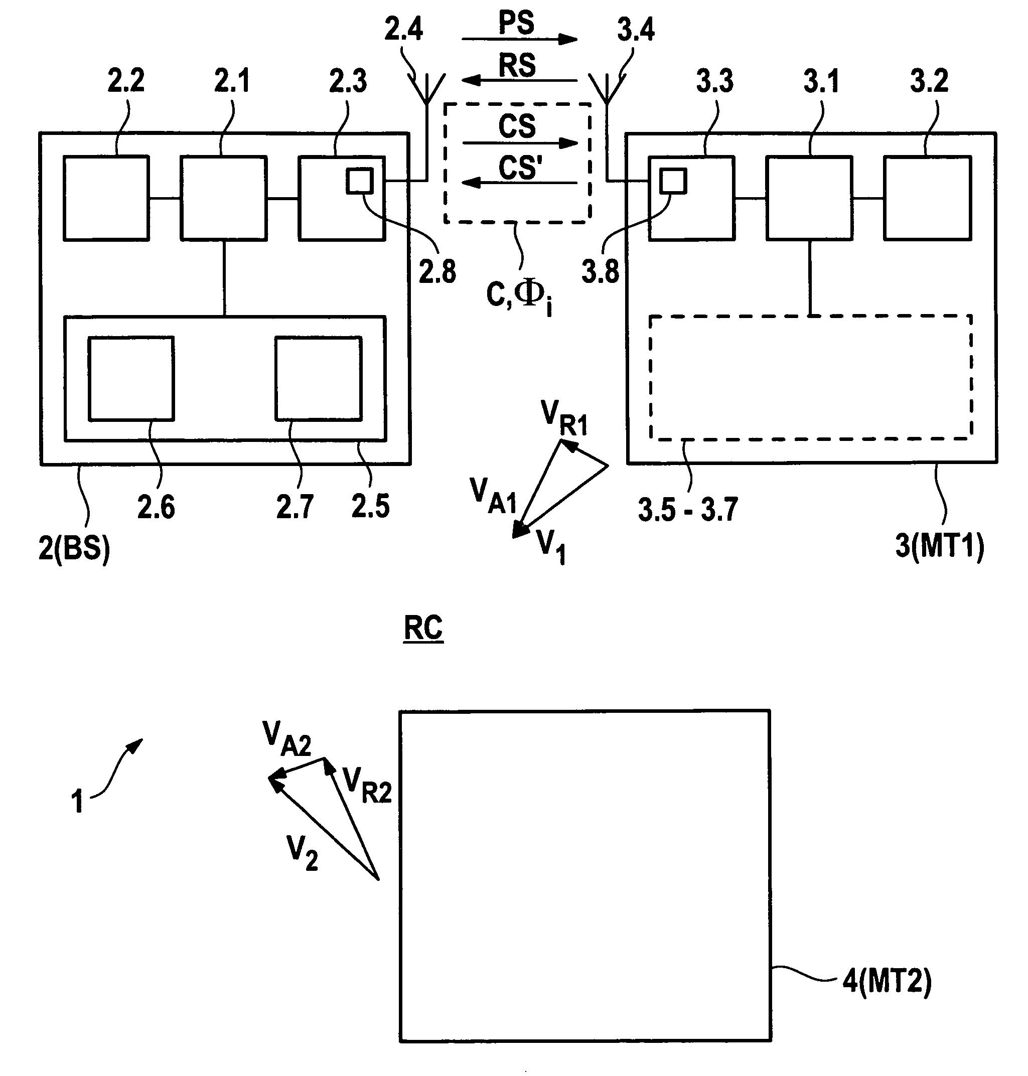
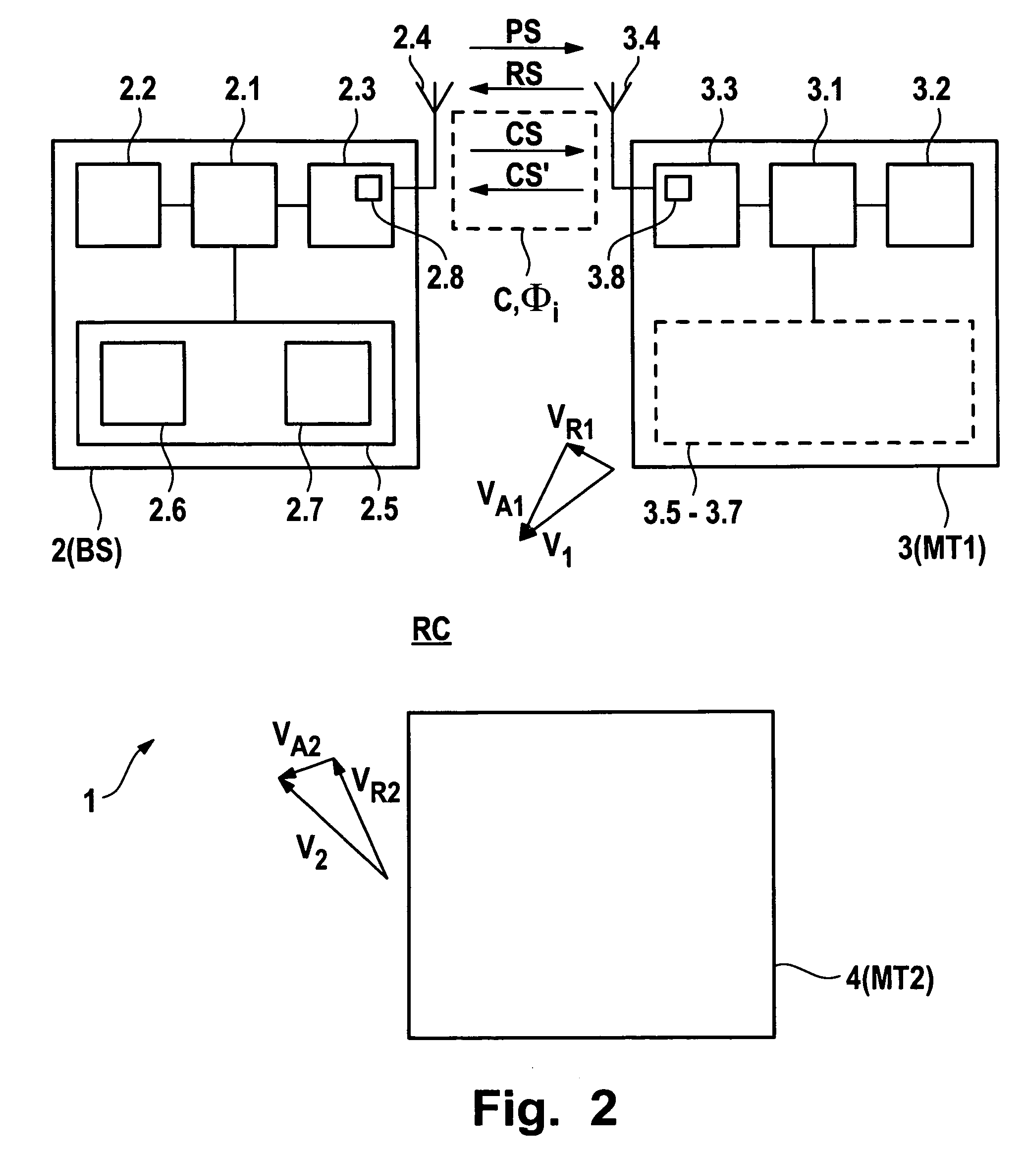
[0045] In an embodiment of the system according the present invention the adaptation means, the determining means, and the adjusting means are comprised in the transmitter unit, which—in a further embodiment of the system according the present invention—is a stationary unit, e.g. an access point or a base station, such that the necessary additional equipment can be implemented without excessive difficulties in terms of weight, construction space, or the like. Correspondingly, the receiver unit can take the form of a mobile terminal.

Problems solved by technology

However, such an approach is a drawback in situations where faster adaptation is required, e.g. in heavily varying environments.
If the corresponding adaptation and signaling algorithms are performed needlessly, this corresponds to a effective waste of communication system resources.

Method used


Image

  • System and method for adapting system parameters in radio based communications systems
  • System and method for adapting system parameters in radio based communications systems
  • System and method for adapting system parameters in radio based communications systems

Examples


second embodiment

[0070] An alternative approach to the problem of determining the distance D is depicted in FIG. 4, which is essentially similar to above-described FIG. 3. FIG. 4 shows a schematic diagram of the radio based communications system 1 in accordance with the present invention, wherein the system 1, i.e. the receiver unit 3 is in operative connection with a satellite-based positioning system SPS such as GPS. Accordingly, the inventive system is adapted to perform the following steps to determine the distance D (or the corresponding propagation time T):One of the units 2, 3, e.g. the receiver unit 3, receives data POS indicative of its own absolute position from the satellite-based positioning system SPS. The receiver unit 3 forwards its position data POS to the transmitter unit 2, and the transmitter unit 2 determines the distance D to the receiver unit 3 taking into account its own absolute position, which can either be fixed in the case of a stationary base station or changing, in which...

third embodiment

[0071]FIG. 5 shows a schematic diagram of the radio based communications system 1 in accordance with the present invention, wherein at least the receiver unit 3 further comprises means 3.9 for measuring longitudinal and angular acceleration, in particular an inertial-sensor system. Provided the transmitter unit 2 has knowledge about the absolute start position of the mobile receiver unit 3, e.g. by means of a position update, the receiver unit 3 then measures its longitudinal and angular acceleration in connection with a motion in the direction of arrow M, the new position of the receiver unit 3 being illustrated by means of a dashed box, and determines its displacement by integration over a time interval. The receiver unit 3 then informs the transmitter unit 2 about said displacement since the last position update by transmitting corresponding displacement data DIS. Using said displacement data DIS the transmitter unit 2 determines the new position of the receiver unit 3, e.g. the ...


PUM


Abstract

A method for adapting at least one system parameter (φi) defining a connection (C) between a transmitter unit (2) and a receiver unit (3, 4) in a radio based communications system (1), wherein an adaptation frequency (ν) at which the system parameter(φi) is adapted is dependent on at least one derivative of order n, n=0; 1, of a distance (D) between the transmitter unit (2) and the receiver unit (3, 4) with respect to time. Thus, the method provides an efficient way of relating the need to update system parameters in radio based communications systems to physically measured quantities in connection with constituents of said system, such that the parameter adaptation rate itself is adapted dynamically and system resources can be used in an optimized fashion.

Description

[0001] The invention is based on a priority application 05292047.7 which is hereby incorporated by reference. TECHNICAL FIELD OF INVENTION [0002] The present invention relates generally to radio based communications systems, in particular—but not exclusively—for mobile communication. More specifically, the present invention relates to a method and a system for adapting system parameters in radio based communications systems. BACKGROUND OF THE INVENTION [0003] During operation of radio based communications systems, due to a temporally and spatially varying environment many system parameters have to be adjusted to ensure a high quality of service during a communication session. Examples of such system parameters which generally define a connection between a transmitter unit, e.g. an access point or a base station, and a receiver unit, e.g. a mobile terminal, are output power, modulation format, coding scheme, etc. Today, the adaptation of system parameters in radio based communication...

Claims


Application Information

Patent Timeline
IPC IPC(8): H04B7/24
CPCH04L1/0001H04L1/0015H04L1/0021H04L1/0027
Inventor SCHREIBER, GERHARD
Owner ALCATEL LUCENT SAS
Learn More