
System and method for communicating command parameters between a processor and a memory flow controller

a command parameter and memory flow controller technology, applied in the field of data processing system and method, can solve the problems of limited ineffective work done by pu, and inability to use local memory for other pu functions, so as to reduce the burden on the local store of the processor and minimize the effect of bus traffi

Inactive Publication Date: 2007-04-05
GERHARDT DIANA R +1
View PDF10 Cites 21 Cited by
  • Summary
  • Abstract
  • Description
  • Claims
  • Application Information

AI Technical Summary

Benefits of technology

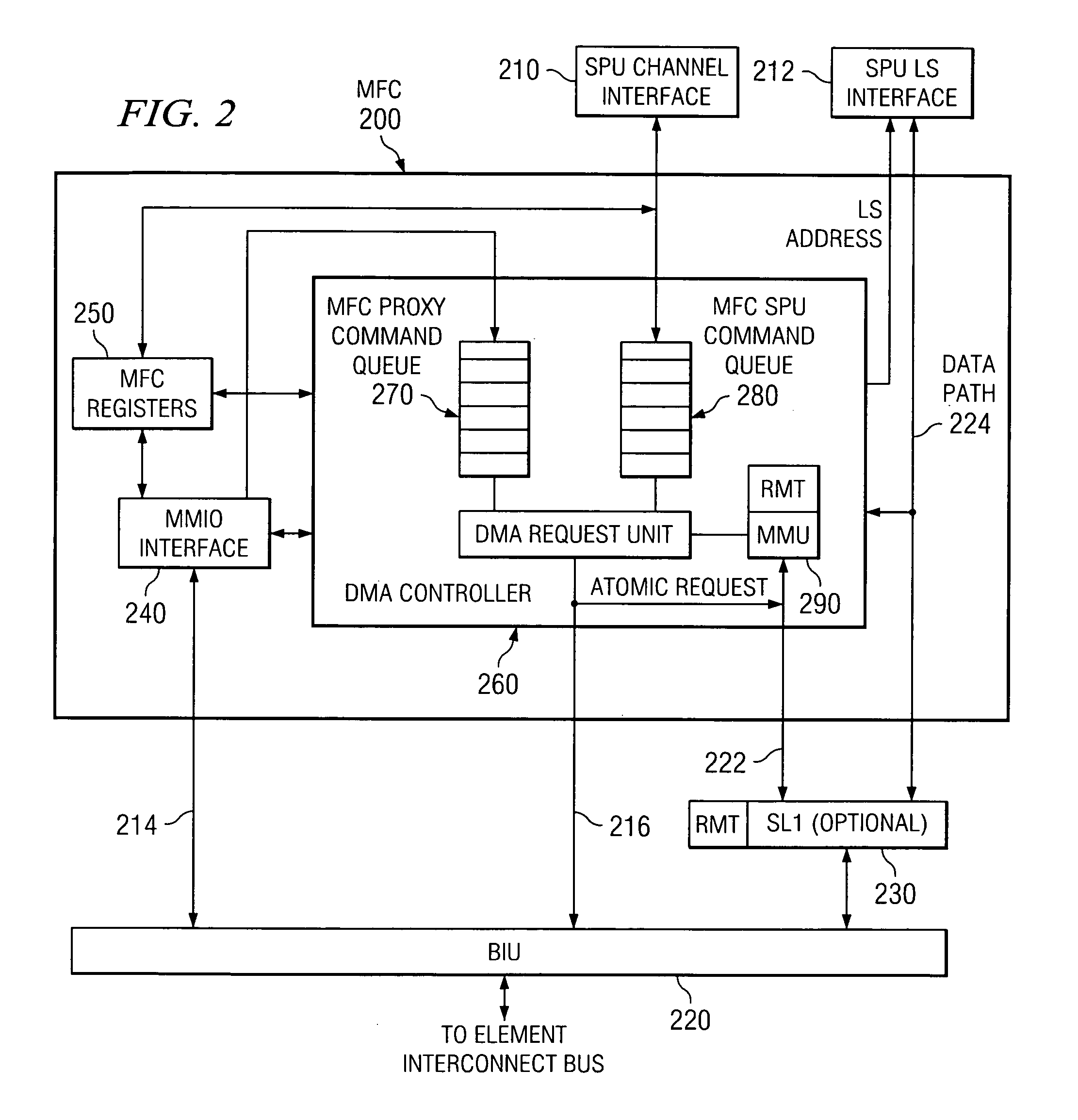
[0008] The present invention provides a system and method for communicating command parameters between a processor and a memory flow controller. The system and method of the present invention make use of a channel interface as the primary mechanism for communicating between the processor and a memory flow controller. The channel interface provides channels for communicating with processor facilities, memory flow control facilities, machine state registers, and external processor interrupt facilities, for example. These channels serve to reduce the burden on the processor's local store as well as minimize bus traffic.

Problems solved by technology

While the program is operating, the PU is polling the event register and is not doing useful work.
Thus, the use of local memory for other PU functions is limited while awaiting response from an external device.
If a PU is simultaneously awaiting communication responses from several devices, the available memory for other functions is even further limited.

Method used


Image

  • System and method for communicating command parameters between a processor and a memory flow controller
  • System and method for communicating command parameters between a processor and a memory flow controller
  • System and method for communicating command parameters between a processor and a memory flow controller

Examples


Embodiment Construction

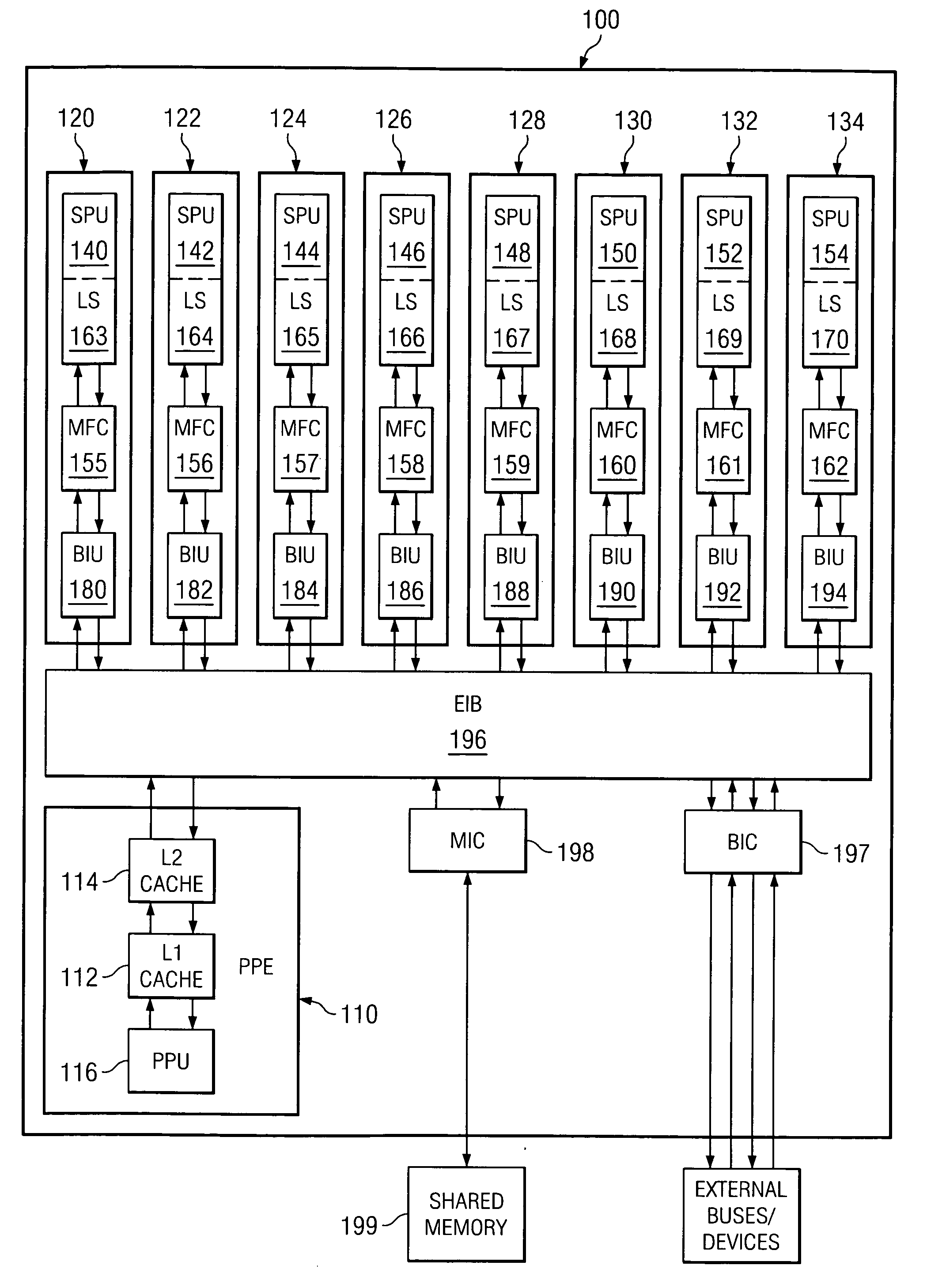
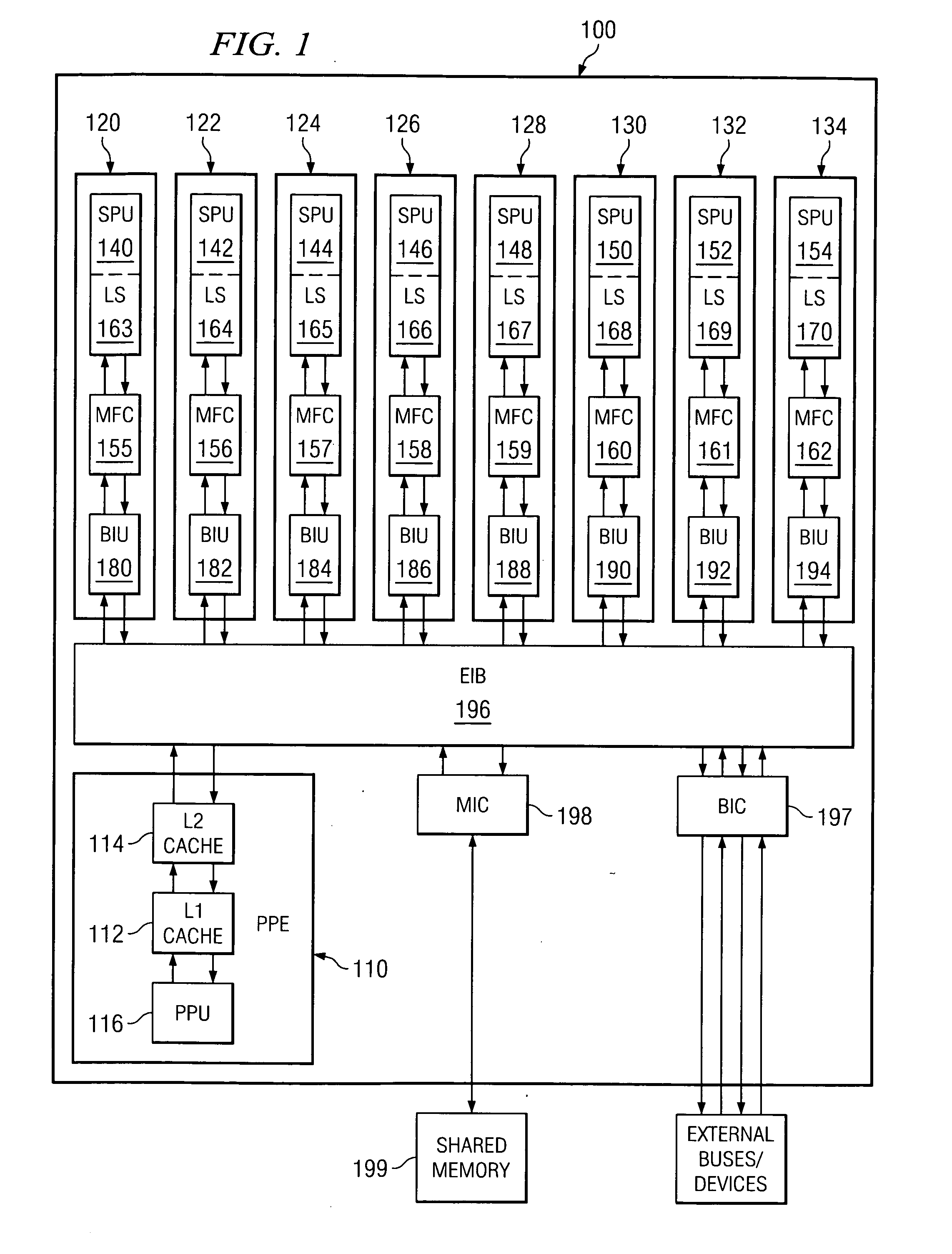
[0068]FIG. 1 is an exemplary block diagram of a data processing system in which aspects of the present invention may be implemented. The exemplary data processing system shown in FIG. 1 is an example of an implementation of the heterogenous Broadband Processor Architecture, such as the CELL Broadband Engine processor available from International Business Machines, Inc. While the Broadband Processor Architecture (BPA) will be used in the description of the preferred embodiments of the present invention, the present invention is not limited to such, as will be readily apparent to those of ordinary skill in the art upon reading the following description.

[0069] As shown in FIG. 1, the BPA 100 includes a heterogenous arrangement of power processor element (PPE) 110 having a processor (PPU) 116 and its L1 and L2 caches 112 and 114, and multiple synergistic processor elements (SPEs) 120-134 each of which has its own processor unit (SPU) 140-154, memory flow control (MFC) 155-162, local me...


PUM


Abstract

A system and method for communicating command parameters between a processor and a memory flow controller are provided. The system and method make use of a channel interface as the primary mechanism for communicating between the processor and a memory flow controller. The channel interface provides channels for communicating with processor facilities, memory flow control facilities, machine state registers, and external processor interrupt facilities, for example. These channels may be designated as blocking or non-blocking. With blocking channels, when no data is available to be read from the corresponding registers, or there is no space available to write to the corresponding registers, the processor is placed in a low power “stall” state. The processor is automatically awakened, via communication across the blocking channel, when data becomes available or space is freed. Thus, the channels of the present invention permit the processor to stay in a low power state.

Description

BACKGROUND OF THE INVENTION [0001] 1. Technical Field [0002] The present invention relates generally to an improved data processing system and method. More specifically, the present invention is directed to a system and method for communicating command parameters between a processor and a memory flow controller. [0003] 2. Description of Related Art [0004] Normally, in the prior art, when a CPU or other processing unit (PU) is waiting upon some event external to the program, the operating system or an active program will run a poll loop where it will keep reading an event register, utilized by the PU in connection with the program, until the event that it is waiting upon occurs. While the program is operating, the PU is polling the event register and is not doing useful work. [0005] Typical modern processors often use virtual memory and the memory mapping of external devices for this communication. On the other hand, some processors, especially in a multiprocessor environment, only h...

Claims


Application Information

Patent Timeline
Patent Type & Authority Applications(United States)
IPC IPC(8): G06F13/00
CPCG06F13/1642G06F13/32
Inventor DAY, MICHAEL N.JOHNS, CHARLES R.LIU, PEICHUN P.SWANSON, TODD E.TRUONG, THUONG Q.
Owner GERHARDT DIANA R
Learn More