Patient lift and transfer device

a technology for lifting and transferring patients, applied in the field of moving objects, can solve the problems of exacerbated problems, further discomfort, and -rotating belt designs

Inactive Publication Date: 2007-04-12
MEDIGLIDER
View PDF35 Cites 20 Cited by
  • Summary
  • Abstract
  • Description
  • Claims
  • Application Information

AI Technical Summary

Benefits of technology

[0011] It is therefore one object of the present invention to provide an improved method and device for transporting an object such as a patient from one location to another.

Problems solved by technology

There can still be problems, however, in getting a patient from a bed or other support surface onto a stretcher or gurney.
This problem is exacerbated when the patient is unusually heavy.
This approach can still be difficult if the patient is uncooperative, and can further be very uncomfortable even if the patient is cooperative, due to the frictional engagement of the tray with the body or the lack of firm support by the sheet.
There are still several serious problems with the counter-rotating belt designs.
Because of this limitation, such devices cannot be used in all settings, i.e., wherein there is insufficient clearance space under the bed or table (a situation becoming more common as more accouterments are added to beds and tables that occupy the space underneath).
These devices further only allow loading and unloading along one side of the device, which can present problems when the patient is not suitably oriented (head-to-feet) on the device with respect to the bed or table.
Designs such as that shown in the '321 patent are also not particularly comfortable as there is only a thin layer of the belt interposed between the patient and the hard surface of the metal support trays.
Moreover, hospitals are becoming increasingly concerned with potential contamination from patient fluids, and the prior art belt-type transfer devices are difficult if not impossible to properly clean.

Method used


Image

  • Patient lift and transfer device
  • Patient lift and transfer device
  • Patient lift and transfer device

Examples


Embodiment Construction

)

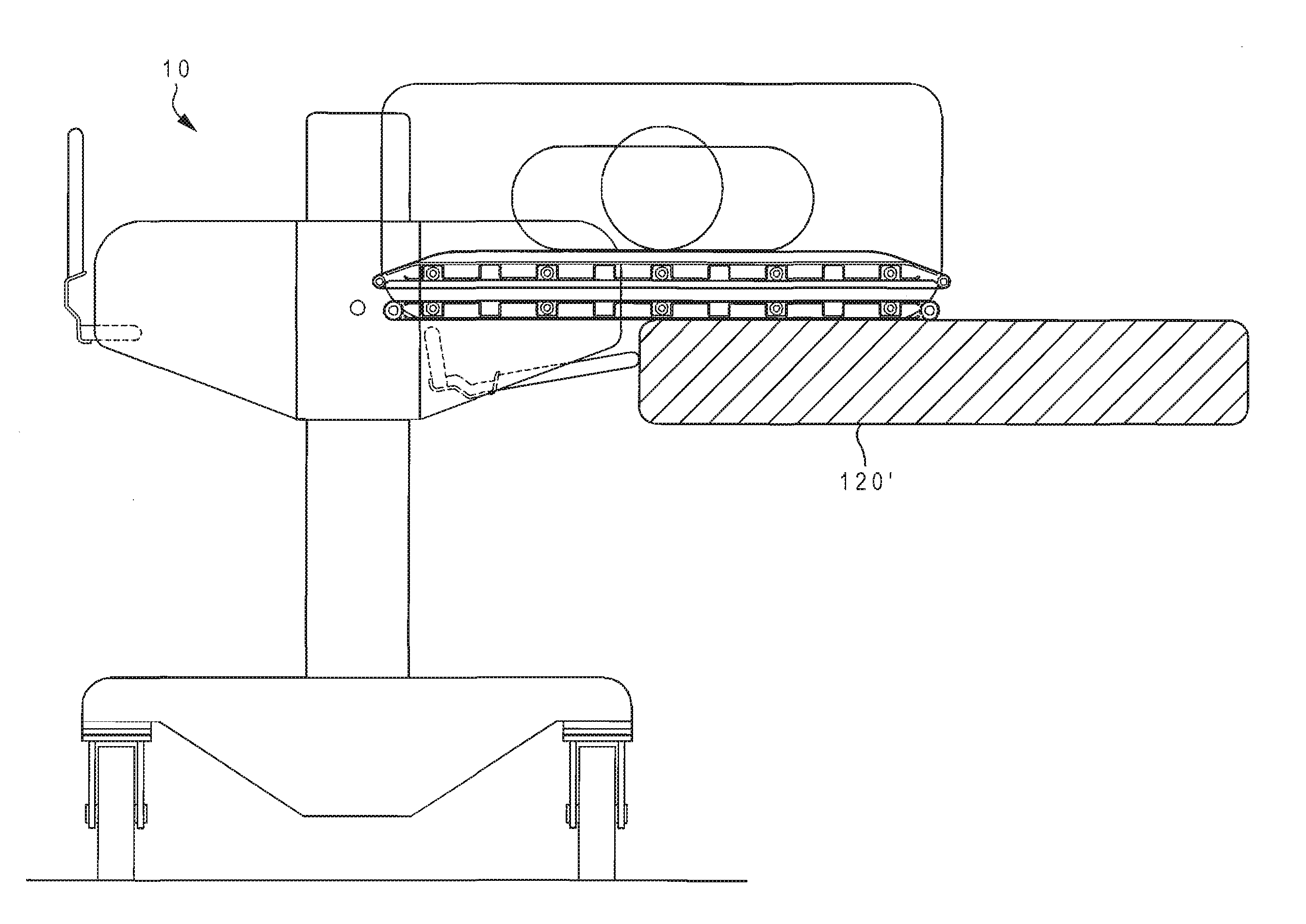
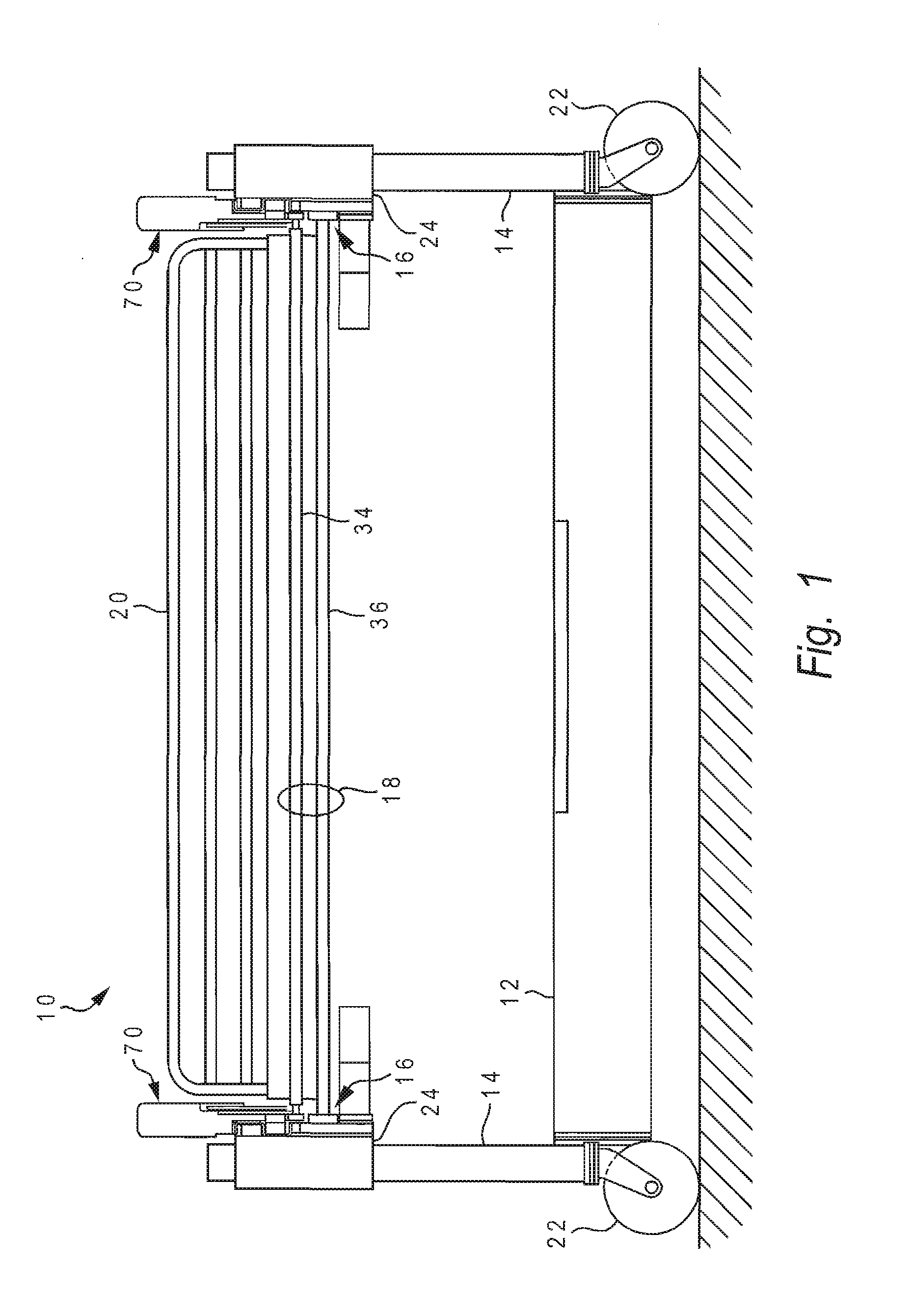
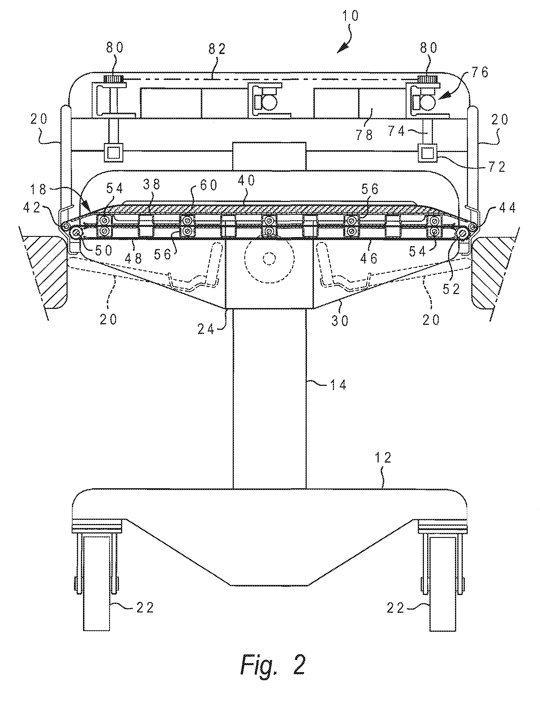
[0035] With reference now to the figures, and in particular with reference to FIGS. 1-3, there is depicted one embodiment 10 of a patient lift and transfer device constructed in accordance with the present invention. Patient lift and transfer device 10 is generally comprised of a frame or base 12, two vertical support columns 14 mounted on base 12, a horizontal slide assembly 16 attached to support columns 14, a table assembly 18 attached to slide assembly 16, and side rails 20 attached to support columns 14.

[0036] Base 12 is generally rectangular in shape when viewed from above, and extends the full length of device 10. Base 12 is constructed of any durable material, preferably a fairly dense metal or metal alloy such as stainless steel to help anchor the device. Four wheels or pivoting casters 22 are attached to base 12, one at each corner, and provide a clearance space of about three inches between the bottom of base 12 and the floor. Casters 22 are preferably large-diameter, l...


PUM


Abstract

A patient transfer device has four casters and two counter-rotating steering wheels. The steering wheels provide a turning path whose center of curvature lies along a transverse centerline of the device. A foot pedal selectively lifts the steering wheels off the floor or brakes them. Another foot pedal at a back end of the device can lock the casters at the front end in a straight direction. The transfer table of the device may be inclined either longitudinally or transversely, and has an upper table whose edge rollers retract to introduce slack in the upper belt so that an air mattress can be inflated. The upper belt selectively disengages from the lower belt using movable, pneumatically-actuated pinch rollers. The outer surface of the upper belt is rough while the outer surface of the lower belt is smooth. The belts are constructed of a material which includes an antimicrobial agent.

Description

CROSS-REFERENCE TO RELATED APPLICATION [0001] This application is a continuation-in-part of U.S. patent application Ser. No. 11 / 246,426 entitled “PATIENT LIFT AND TRANSFER DEVICE” filed Oct. 7, 2005, which is hereby incorporated.BACKGROUND OF THE INVENTION [0002] 1. Field of the Invention [0003] The present invention generally relates to devices for moving objects, and more specifically to a method and device for transferring mobility-impaired persons, such as moving a patient from a bed to a table. [0004] 2. Description of the Related Art [0005] A wide variety of products have been designed to move objects from one location to another and, in particular, transfer mobility-impaired individuals such as patients. In a hospital setting, patients must often be transported from their beds to an examination table or operating table, and back again. Basic devices for transferring patients include stretchers that are carried manually by two attendants, and wheeled gurneys that can more easi...

Claims


Application Information

Patent Timeline
Patent Type & Authority Applications(United States)
IPC IPC(8): A61G7/14
CPCA61G7/1019A61G7/1032A61G2203/723A61G7/1057A61G2200/32A61G7/1046A61G7/053A61G7/10
Inventor PATTERSON, RICHARD A.SMUCKER, RALPH M.
Owner MEDIGLIDER
Why Eureka
Try Eureka