Stent loader

a technology of stent and crimping device, which is applied in the direction of prosthesis, manufacturing tools, blood vessels, etc., can solve the problems of reducing the size of the stent, damage to the stent, coating and/or the crimping device, and the presence of coatings, so as to reduce the diameter of the stent and increase the size of the crimping chamber. , the effect of reducing the size of the crimping chamber

Inactive Publication Date: 2007-04-12
BOSTON SCI SCIMED INC
View PDF22 Cites 49 Cited by
  • Summary
  • Abstract
  • Description
  • Claims
  • Application Information

AI Technical Summary

Benefits of technology

[0012] In at least one embodiment, the invention is directed to a method of loading a self-expanding stent which includes providing a crimping device having a crimping chamber constructed and arranged to reduce the diameter of a stent. A support device is be provided to support a delivery device having an internal diameter. The support device is constructed and arranged to move the delivery device with respect to the crimping device, and the delivery device is oriented to receive a stent from said crimping device. A fluid source is provided and arranged to direct a fluid flow through the crimping chamber of the crimping device. The fluid is provided at a temperature lower than an ambient temperature and is desirably capable of placing a shape memory material into a martensitic state. A self-expanding stent is provided and oriented within the crimping chamber of the crimping device. Fluid flow is directed through the crimping chamber of the crimping device. The size of the crimping chamber is reduced to reduce an outer diameter of the stent to less than the internal diameter of the delivery device. The size of the crimping chamber is increased, wherein said fluid flow advances the stent such that at least a portion of the stent exits the crimping chamber and enters the delivery device. A step procedure is performed wherein the delivery device is moved away from the crimping device, thereby moving another portion of the stent out of the crimping chamber. The size of the crimping chamber is again reduced to reduce the portion of the stent oriented within the crimping chamber to an outer diameter less than the internal diameter of the delivery device. The delivery device is moved back toward the crimping device, thereby further advancing the stent into the sheath. In the event that a portion of the stent is still oriented within the crimping chamber, the size of the crimping chamber may again be increased, and the step procedure may be repeated as necessary until the entire stent is oriented within the sheath.

Problems solved by technology
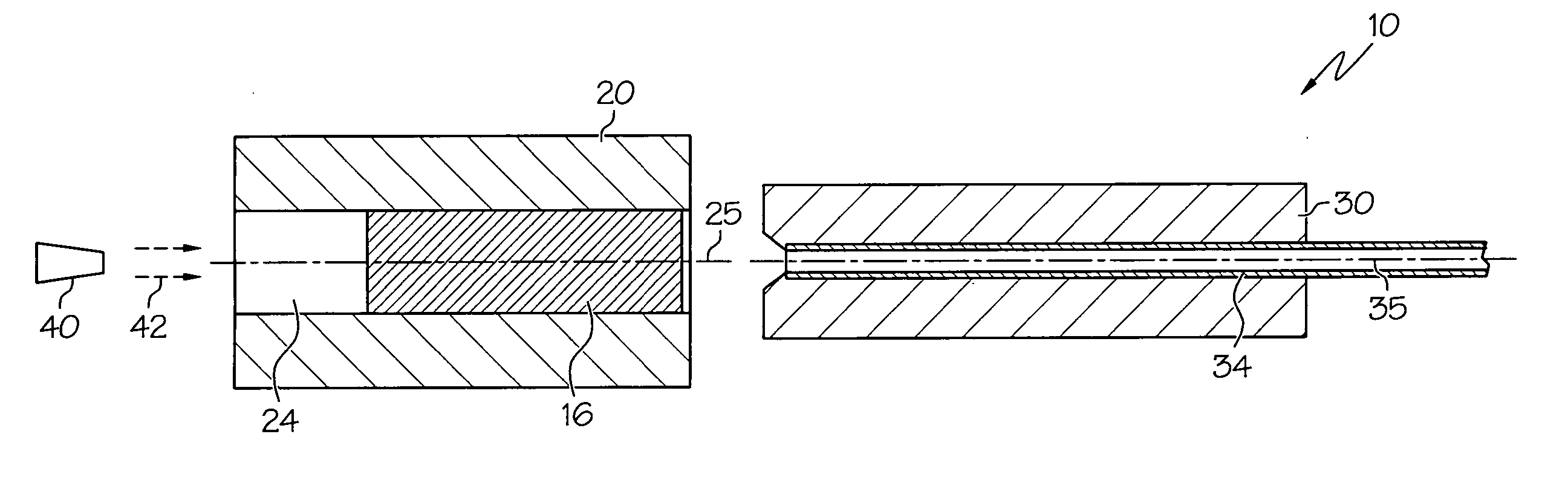
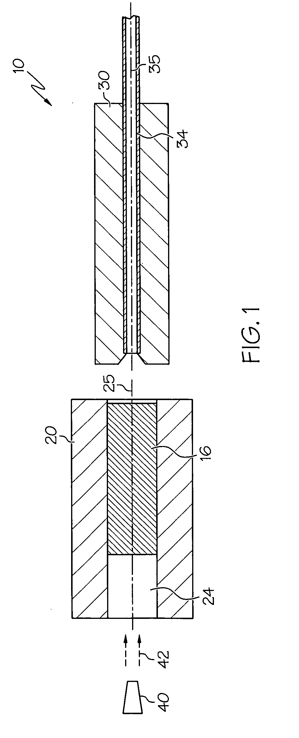
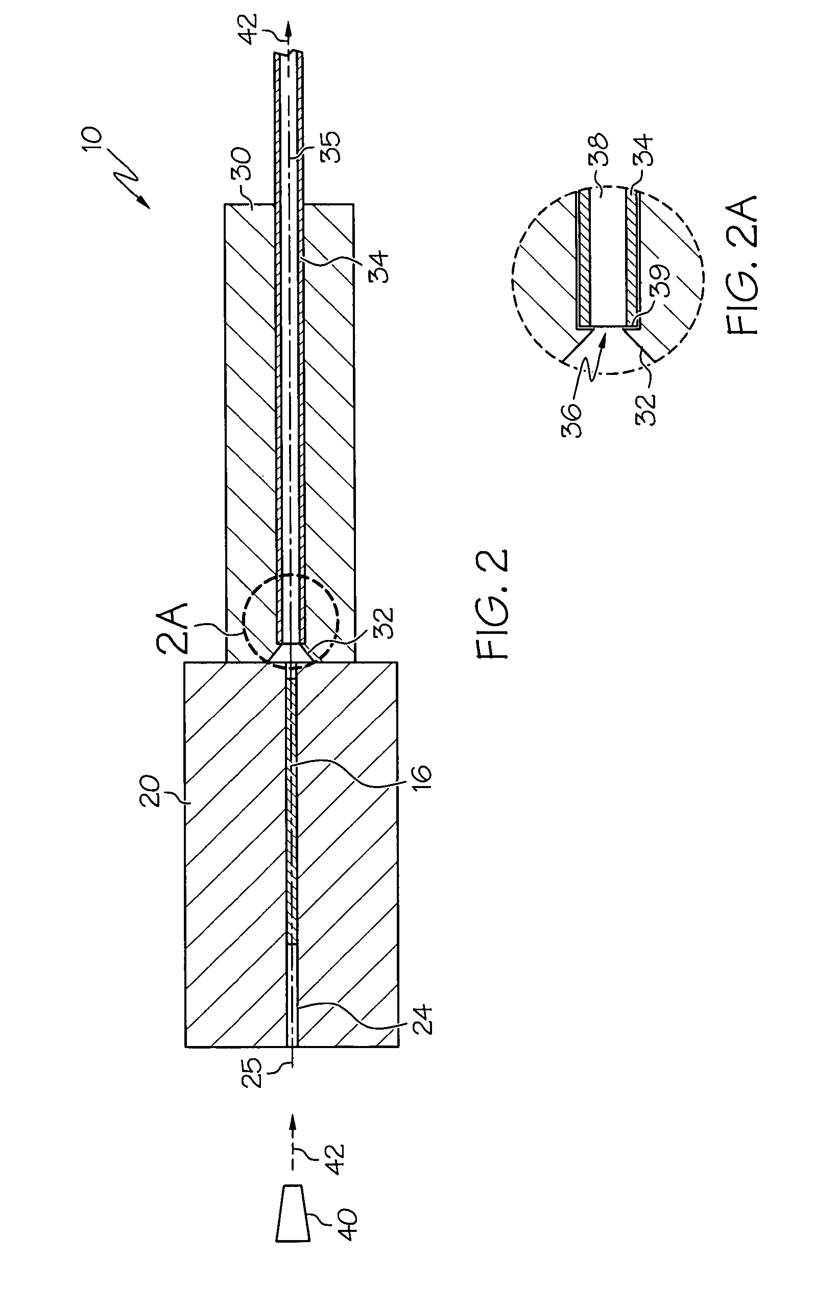
The presence of a coating may complicate procedures for reducing the size of a stent and loading the stent into a delivery system, especially when the stent is relatively long and / or when the stent is self-expanding.
Sliding friction between the crimping device and the stent or coating may cause damage to the stent, coating and / or the crimping device.

Method used


Image

  • Stent loader
  • Stent loader
  • Stent loader

Examples


example 1

[0058] Twelve examples of self-expanding stents of size 10×103 mm were successfully loaded into delivery devices under the following conditions.

Settings for ExperimentCrimp Velocity =32.8mm / secFire Size =1.6mmCrimp Force =70LbsStent Chill Size =10mmE-Tube chilling time =2secIris Chilling size =1.8mmE-Tube Diameter =6FrenchStep Distance =5mmAverageNumber ofTemperatureLoading AirStent Length WhenStentCrimps(degrees C.)Pressure (psi)Loaded (mm)15−1810.49106.524−1910.49Pass through34−1710.49106.544−2010.78106.554−1710.5106.565−1810.5106.574−1710.5106.585−1210.5106.598−2410.5106.7108−2010.5106.5118−1810.6106.7129−2010.5106.5

example 2

[0059] Twelve examples of self-expanding stents of size 12×60 mm were

Settings for ExperimentCrimp Velocity =32.8mm / secFire Size =1.6mmCrimp Force =70LbsStent Chill Size =10mmE-Tube chilling time =2secIris Chilling size =1.8mmE-Tube Diameter =6FrenchStep Distance =5mmAverageStent LengthNumber ofTemperatureLoading AirWhen LoadedStentCrimps(degrees C.)Pressure (psi)(mm)15−2510.1962.825−1910.196335−1510.4962.944−1910.1962.954−1910.49Pass through65−1610.4962.974−1610.786383−2010.196394−2010.1963103−2310.1963.2114−2510.1963124−2510.19Pass through

example 3

[0060] Twelve examples of self-expanding stents of size 7×125 mm were successfully loaded into delivery devices under the following conditions.

Settings for ExperimentCrimp Velocity =32.8mm / secFire Size =1.6mmCrimp Force =60LbsStent Chill Size =10mmE-Tube chilling time =2secIris Chilling size =1.8mmE-Tube Diameter =6FrenchStep Distance =2.5mmAverageNumber ofTemperatureLoading AirStent Length WhenStentCrimps(degrees C.)Pressure (psi)Loaded (mm)14−3911.2313025−3511.0713036−3511130.544−3411.113054−3411129.864−3811.07129.2274−3911129.285−38.211.36129.295−39.511.07129.2106−4011.07129119−3611.01129125−4211.2129


PUM

PropertyMeasurementUnit
lengthaaaaaaaaaa
pressuresaaaaaaaaaa
volumeaaaaaaaaaa

Abstract

A stent loading device may comprise a stent crimping device, a fluid source and a support device arranged to support and move a stent delivery device. The fluid source may provide chilled fluid capable of placing a shape memory material into a martensitic state. After stent crimping, as the crimping device opens, the fluid flow may advance at least a portion of the stent into the delivery device. A step procedure may be used to move the rest of the stent into the delivery device, wherein the delivery device may be moved away from the crimping device, the portion of the stent still in the crimping device may be crimped again, and the delivery device may be moved back to its original position, thereby stepping another portion of the stent into the delivery device. The step procedure may be repeated until the entire stent is oriented within the delivery device.

Description

FIELD OF THE INVENTION [0001] In some embodiments this invention relates to implantable medical devices, their manufacture, and methods of use. Some embodiments are directed to delivery systems, such as catheter systems of all types, which are utilized in the delivery of such devices. BACKGROUND OF THE INVENTION [0002] A stent is a medical device introduced to a body lumen and is well known in the art. Typically, a stent is implanted in a blood vessel at the site of a stenosis or aneurysm endoluminally, i.e. by so-called “minimally invasive techniques” in which the stent in a radially reduced configuration, optionally restrained in a radially compressed configuration by a sheath and / or catheter, is delivered by a stent delivery system or “introducer” to the site where it is required. The introducer may enter the body from an access location outside the body, such as through the patient's skin, or by a “cut down” technique in which the entry blood vessel is exposed by minor surgical ...

Claims


Application Information

Patent Timeline
Patent Type & Authority Applications(United States)
IPC IPC(8): B23P11/00B21D39/00
CPCA61F2/95A61F2002/9522A61F2310/0097Y10T29/5383Y10T29/53065Y10T29/49913Y10T29/49908Y10T29/49911A61F2/9522
Inventor SERRANO, GABRIEL SOBRINO
Owner BOSTON SCI SCIMED INC
Why Eureka
Try Eureka