
Fluoropolymer Fiber Composite Bundle

a fluoropolymer and fiber bundle technology, applied in the direction of yarn, braid, transportation and packaging, etc., can solve the problems of reducing the life of the rope, lcp fibers are particularly susceptible to this failure mechanism, and the fiber bundle is subject to high tensile and bending stresses, so as to reduce the abrasion- or friction-related wear of the fiber bundle and maintain the strength of the fiber bundle

Inactive Publication Date: 2007-04-12
WL GORE & ASSOC INC
View PDF45 Cites 49 Cited by
  • Summary
  • Abstract
  • Description
  • Claims
  • Application Information

AI Technical Summary

Benefits of technology

The present invention provides a composite bundle for repeated stress applications that includes at least one high strength fiber and at least one fluoropolymer fiber. The amount of fluoropolymer fiber present in the bundle is about 40% by weight or less. The high strength fiber can be liquid crystal polymer or ultrahigh molecular weight polyethylene, or a combination of both. The fluoropolymer fiber can be an ePTFE fiber, which can be a monofilament or multifilament, either low or high density. The composite bundle has a ratio of break strengths after abrasion test of at least 1.8, preferably 3.8, or 4.0. The fluoropolymer fiber can also include a filler or lubricant. The invention also provides a method of reducing abrasion- or friction-related wear of a fiber bundle in repeated stress applications while maintaining the strength of the bundle by including at least one filament of fluoropolymer. The invention also provides various products made from the inventive composite bundle, such as rope, belt, net, sling, cable, woven fabric, nonwoven fabric, or tubular textile.

Problems solved by technology

They are subjected to high tensile and bending stresses in use as well as a wide range of environmental challenges.
The abrasion damages the fibers, thereby decreasing the life of the rope.
LCP fibers are particularly susceptible to this failure mechanism.
This internal heat severely weakens the fibers.
The UHMWPE fibers suffer from this mode of failure.
All such ropes, however, still perform inadequately in some applications, failing due to one or more of the three above-mentioned mechanisms.
For example, UHMWPE fibers and high strength fibers, such as LCP fibers, have been blended to create a large diameter rope with better abrasion resistance, but they are still not as effective as desired.
Typically such coatings wear off relatively quickly.
Jackets add weight, bulk, and stiffness to the rope, however.
In sum, none of the known attempts to improve the life of ropes or cable have provided sufficient durability in applications involving both bending and high tension.

Method used

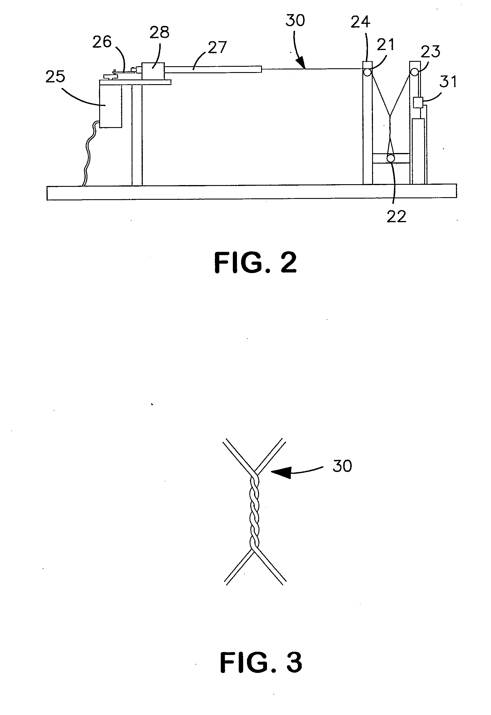

Image

  • Fluoropolymer Fiber Composite Bundle
  • Fluoropolymer Fiber Composite Bundle
  • Fluoropolymer Fiber Composite Bundle

Examples


example 1

[0049] A single ePTFE fiber was combined with a single liquid crystal polymer (LCP) fiber (Vectran®, Celanese Acetate LLC, Charlotte, N.C.) and subjected to the afore-mentioned abrasion test. The results from this test were compared against the results from the test of a single LCP fiber.

[0050] An ePTFE monofilament fiber was obtained (HT400d Rastex® fiber, W.L. Gore and Associates, Inc., Elkton Md.). This fiber possessed the following properties: 425 d weight per unit length, 2.29 kg break force, 5.38 g / d tenacity and 1.78 g / cc density. The LCP fiber had a weight per unit length of 1567 d, a 34.55 kg break force, and a tenacity of 22.0 g / d.

[0051] The two fiber types were combined by simply holding them so that they were adjacent to one another. That is, no twisting or other means of entangling was applied. The weight percentages of these two fibers when combined were 79% LCP and 21% ePTFE. The weight per unit length of the composite bundle was 1992 d. The break force of the compo...

example 2a

[0058] A single ePTFE monofilament fiber was combined with a single ultra high molecular weight polyethylene (UHMWPE) fiber (Dyneema® fiber, DSM, Geleen, the Netherlands). Abrasion testing was performed as previously described. The composite bundle test results were compared to the results from the test of a single UHMWPE fiber.

[0059] An ePTFE monofilament fiber as made and described in Example 1 was obtained. The two fiber types were combined by simply holding them so that they were adjacent to one another. That is, no twisting or other means of entangling was applied. The weight percentages of these two fibers when combined were 79% UHMWPE and 21% ePTFE. The weights per unit length of the UHMWPE and the composite bundle were 1581 d and 2006 d, respectively. The break forces of the UHMWPE and the composite bundle were 50.80 kg and 51.67 kg, respectively. The tenacities of the UHMWPE and the composite bundle were 32.1 g / d and 25.7 g / d, respectively. Adding the ePTFE fiber to the UH...

example 2b

[0063] A combination of an ePTFE fiber and an UHMWPE fiber was created and tested as described in Example 2a, except that in this case the ePTFE fiber was a multifilament fiber. A 400 d ePTFE monofilament fiber was towed using a pinwheel to create a multifilament ePTFE fiber. The multifilament fiber possessed the following properties: 405 d weight per unit length, 1.18 kg break force, 2.90 g / d tenacity and 0.72 g / cc density.

[0064] One multifilament ePTFE fiber was combined with one UHMWPE fiber as described in Example 2a. The properties and testing results for the UHMWPE fiber are presented in Example 2a. The composite bundle consisted of 80% UHMWPE by weight and 20% ePTFE by weight.

[0065] The weight per unit length of the composite bundle was 1986 d. The break force of the composite bundle was 50.35 kg. The tenacity of the composite bundle was 25.4 g / d. Adding the ePTFE fiber to the UHMWPE fiber changed the weight per unit length, break force, and tenacity by +26%, −1%, and −21%,...


PUM

PropertyMeasurementUnit
densityaaaaaaaaaa
lengthaaaaaaaaaa
speedaaaaaaaaaa

Abstract

A composite bundle for repeated stress applications comprising at least one fiber of a high strength material, at least one fiber of fluoropolymer, wherein the fluoropolymer fiber is present in an amount of about 40% by weight or less.

Description

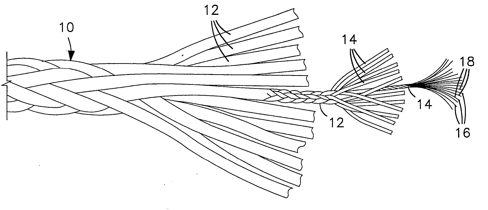
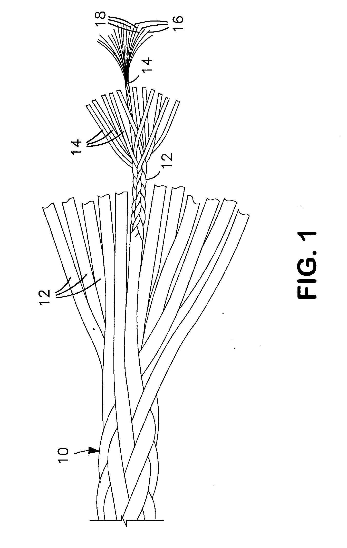
RELATED APPLICATION [0001] The present application is a divisional application of pending U.S. patent application Ser. No. 11 / 056,074 filed Feb. 11, 2005.FIELD OF THE INVENTION [0002] The present invention relates to a fluoropolymer composite bundle and, more particularly, to ropes and other textiles made of composite bundles including fluoropolymers such as polytetrafluoroethylene (PTFE). DEFINITION OF TERMS [0003] As used in this application, the term “fiber” means a threadlike article as indicated at 16 and 18 of FIG. 1. Fiber as used herein includes monofilament fiber and multifilament fiber. A plurality of fibers may be combined to form a “bundle”14 as shown in FIG. 1. When different types of fibers are combined to form a bundle, it is referred to herein as a “composite bundle.” A plurality of bundles may be combined to form a “bundle group”12 as shown in FIG. 1. A plurality of bundle groups may be combined to form a “rope”10 as shown in FIG. 1 (although alternative rope constr...

Claims


Application Information

Patent Timeline
Patent Type & Authority Applications(United States)
IPC IPC(8): D04C1/00
CPCD02G3/047Y10T428/2913D07B2201/2014D07B2201/2036D07B2201/2041D07B2205/2014D07B2205/205D07B2205/2071D07B2205/2096D07B1/025Y10T428/2933D07B2801/10
Inventor BUCHER, RICHARD A.CLOUGH, NORMAN ERNESTEGRES, TAHI K.SASSA, ROBERT L.
Owner WL GORE & ASSOC INC
Learn More