Fuel injection system designed to ensure enhanced reliability of diagnosis of valve

a fuel injection system and reliability technology, applied in the direction of machines/engines, electric control, instruments, etc., can solve problems such as failure to diagnose the pressure-reducing valve, and achieve the effect of improving the reliability of diagnosis of the pressure-reducing valv

Active Publication Date: 2007-04-12
DENSO CORP
View PDF9 Cites 34 Cited by
  • Summary
  • Abstract
  • Description
  • Claims
  • Application Information

AI Technical Summary

Benefits of technology

[0010] It is therefore an object of the invention to provide a fuel injection system which is equipped with a pressure-re...

Problems solved by technology

The fact of such an event is insufficient to make...

Method used


Image

  • Fuel injection system designed to ensure enhanced reliability of diagnosis of valve
  • Fuel injection system designed to ensure enhanced reliability of diagnosis of valve
  • Fuel injection system designed to ensure enhanced reliability of diagnosis of valve

Examples


first embodiment

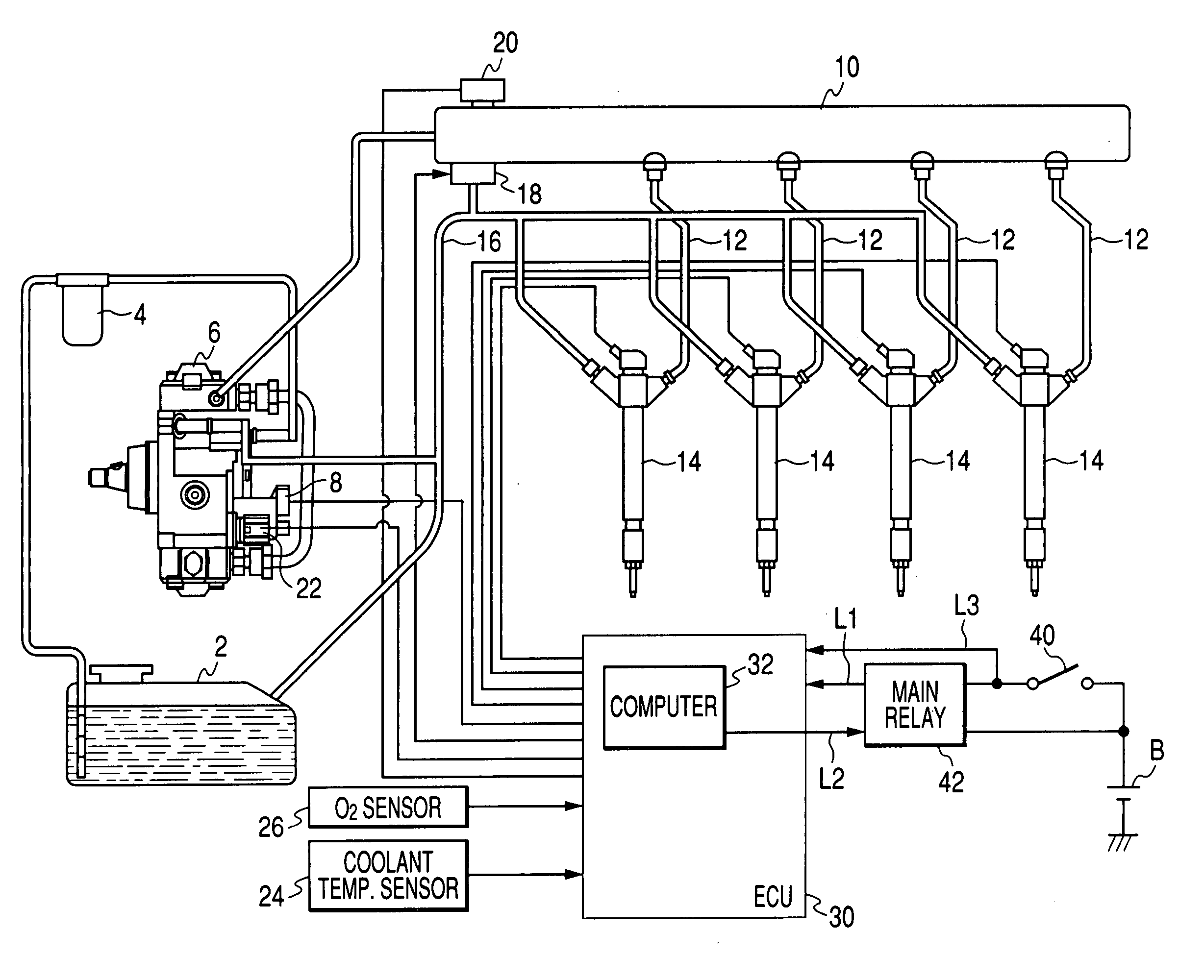
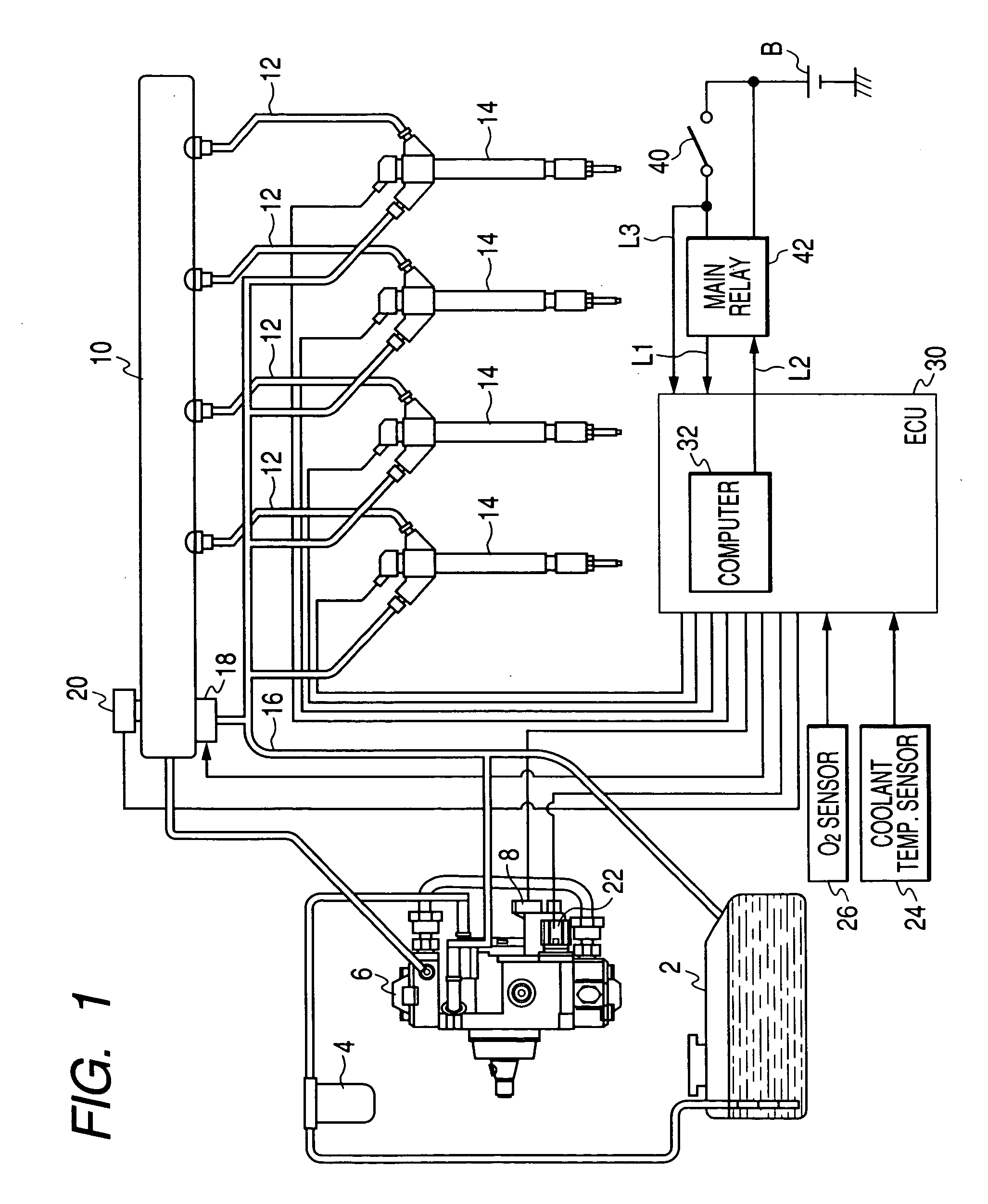
[0039] Referring to the drawings, wherein like reference numbers refer to like parts in several views, particularly to FIG. 1, there is shown a fuel injection system according to the invention which is designed as a common rail fuel injection system (also called an accumulator injection system) working to control injection of fuel into diesel engines for automotive vehicles.

[0040] The fuel injection system includes a fuel pump 6, a common rail 10, fuel injectors 14, a pressure-reducing valve 18, and an electronic control unit (ECU) 30.

[0041] The fuel pump 6 works to pump the fuel out of a fuel tank 2 through a fuel filter 4 and feed it to the common rail 10. The fuel pump 6 is driven by torque of a crankshaft (i.e., an output shaft) of the diesel engine. Specifically, the fuel pump 6 is equipped with a suction control valve 8 which is activated by the ECU 30 to determine the amount of fuel to be discharged from the fuel pump 6. The fuel pump 6 is also equipped with a plurality of p...

second embodiment

[0082] The fuel injection system of the second embodiment will be described below which is designed to determine the threshold α for use in diagnosing the pressure-reducing valve 18 as functions of temperatures of the fuel in the fuel pump 6 and the coolant of the engine as well as the pressure of fuel in the common rail 10.

[0083]FIG. 6 shows a diagnosis program to be executed by the ECU 30 of the fuel injection system of this embodiment to diagnose the pressure-reducing valve 18. This program is performed in step 14 of FIG. 3(a). The same reference numbers as employed in FIG. 4 will refer to the same operations, and explanation thereof in detail will be omitted here.

[0084] After the output of the fuel pressure sensor 20 is sampled when the pressure-reducing valve 18 is opened in step 62, the routine proceeds to step 64a wherein the threshold α is calculated based on the pressure of fuel in the common rail 10, the temperature of the fuel in the fuel pump 6, and the temperature of t...

third embodiment

[0086]FIG. 7 shows a fuel injections system according to the invention which is a modification of the one, as illustrated in FIG. 1. The same reference numbers as employed in FIG. 1 will refer to the same parts, and explanation thereof in detail will be omitted here.

[0087] The ECU 30 is equipped with a soak timer 34 which works to turn on the ECU 30 after the elapse of time, as set by the soak timer 32. Specifically, the soak timer 34 is kept activated even after the ignition switch 40 is turned off to cut a supply of electric power to the ECU 30 and works to count the elapsed time from the turning off of the ECU 30. When the elapsed time, as counted by the soak timer 34, reaches the time, as set by the microcomputer 32, the soak timer 34 starts to supply the electric power from the battery B to the ECU 30.

[0088] FIGS. 8(a) and 8(b) show a flowchart of a diagnostic program to be executed by the ECU 30 at given intervals to diagnose the pressure-reducing valve 18 and the fuel pressu...


PUM


Abstract

A fuel injection system for automotive diesel engine is provided which is equipped with a fuel pressure sensor working to measure the pressure of fuel in an accumulator and a pressure-reducing valve working to drain the fuel from the accumulator. The system is designed to ensure enhanced reliability of diagnosis of the pressure-reducing valve. The system works to make a temporal diagnosis of the pressure-reducing valve based on the behavior of the pressure in the accumulator upon opening of the pressure-reducing valve after an ignition switch is turned off. After elapse of a given period of time, when it is determined that a value of the pressure in the accumulator, as measured by the fuel pressure sensor, lies near the atmospheric pressure, the system determines that the fuel pressure sensor is operating properly and fixes the temporal diagnosis of the pressure-reducing valve ultimately.

Description

CROSS REFERENCE TO RELATED DOCUMENT [0001] The present application claims the benefit of Japanese Patent Application No. 2005-293153 filed on Oct. 6, 2005, the disclosure of which is incorporated herein by reference. BACKGROUND OF THE INVENTION [0002] 1. Technical Field of the Invention [0003] The present invention relates generally to an accumulator fuel injection system equipped with a fuel pressure sensor working to measure the pressure of fuel within an accumulator such as a common rail and a pressure-reducing valve working to reduce the pressure in the accumulator, and more particularly to such a system designed to ensure enhanced reliability of diagnosis of the pressure-reducing valve. [0004] 2. Background Art [0005] Automotive fuel injection systems are known which are equipped with an accumulator (also called a common rail) working to supply fuel at high pressure to fuel injectors each for one of cylinders of a diesel engine. Such common rail fuel injection systems are typic...

Claims


Application Information

Patent Timeline
IPC IPC(8): F02M63/00F02M59/36
CPCF02D41/221F02D41/222F02D41/3863F02D2041/223F02D2200/0602F02D2250/31F02M55/02F02M63/0225F02M63/025F02M65/003
Inventor TAKAHASHI, TOMOHIRO
Owner DENSO CORP
Why Eureka
Try Eureka