
Exhauster for roaster

a technology for exhausting fans and roasters, which is applied in the direction of domestic stoves or ranges, heating types, lighting and heating apparatuses, etc. it can solve the problems of stationary tubes b, wall-mounted fans have a limitation to completely exhaust smoke and smell, and affect the interior appearan

Inactive Publication Date: 2007-04-12
SHIN HYEON GU
View PDF10 Cites 33 Cited by
  • Summary
  • Abstract
  • Description
  • Claims
  • Application Information

AI Technical Summary

Benefits of technology

[0017] To solve the above problems of the conventional art, it is an object of the present invention to provide an exhauster for a roaster, in which a plurality of hood pipes can be telescopically combined to form a hood tube in a multi-stage, to thus make the hood tube completely inserted into a hood main body, a fan built in a hood main body fixed on a ceiling is provided at the side of the hood main body, a space portion in which the completely folded hood tube can be completely buried in the hood main body is formed, and since the exhauster including the hood tube is completely buried and installed into a ceiling slab, to then be hidden, the whole aesthetics in the restaurant are prevented from being degraded due to the exposure of the exhauster.
[0018] It is another object of the present invention to provide an exhauster for a roaster in which packings are applied to connection portions of the respective pipes to thereby prevent a gap from being formed between the connected hood pipes and the leak of the foreign matters from occurring via the connection portions.
[0019] It is still another object of the present invention to provide an exhauster for a roaster in which a diffuser playing a role of an oil receiver is installed in the lowest hood tube with which a hood is connected, to thereby prevent the contaminant streaming down through the inner portion of the hood tube from falling over a roaster roasting the meat, and thus provide a sanitary dining environment.
[0021] a hood tube in which a plurality of hood pipes can be combined so as to be folded in a multi-stage, and packings are applied to connection portions of the respective pipes to thereby prevent a gap from being formed between the connected hood pipes and the leak of the foreign matters from occurring;
[0026] Moreover, a limit switch having a connection structure which is connected with a motor is further installed in the connection portion at which the hood main body and the hood tube are connected, and a remote sensor having an electrical connection structure between the motor and the limit switch is further installed at the side of the hood main body, to thereby be possible to perform a remote control.
[0027] Moreover, bolting holes are formed in both ends of the bracket of the hood main body, stay bolts on all the surfaces of which screw threads are formed are engaged with a pair of screw nuts which are installed in the upper and lower portions around the bracket, and the upper ends of the stay bolts are spirally engaged on the wall surface of a ceiling where the exhauster is installed and then fixed by screw nuts, to thereby minutely adjust height of the hood main body including the bracket and the hood tube according to adjustment of the tightening force of the screw nuts.

Problems solved by technology

However, the wall-mounted fan has a limitation to completely exhaust the smoke and smell which are consistently generated in the process of roasting the meat.
As a result, the smoke including foreign matters remains in the indoor air to thus make the indoor air polluted and sticks to the indoor wall to thus impair the interior appearance.
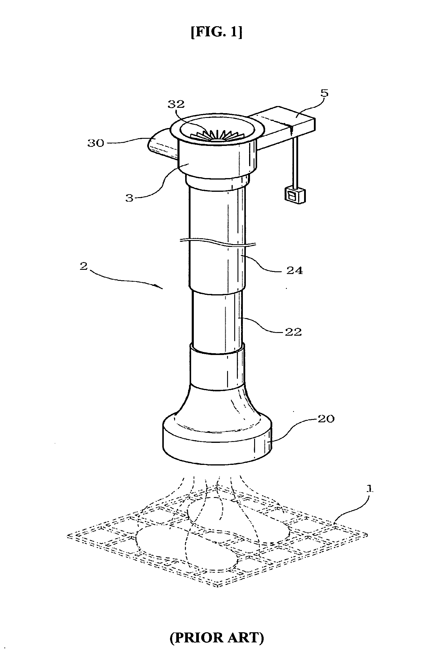
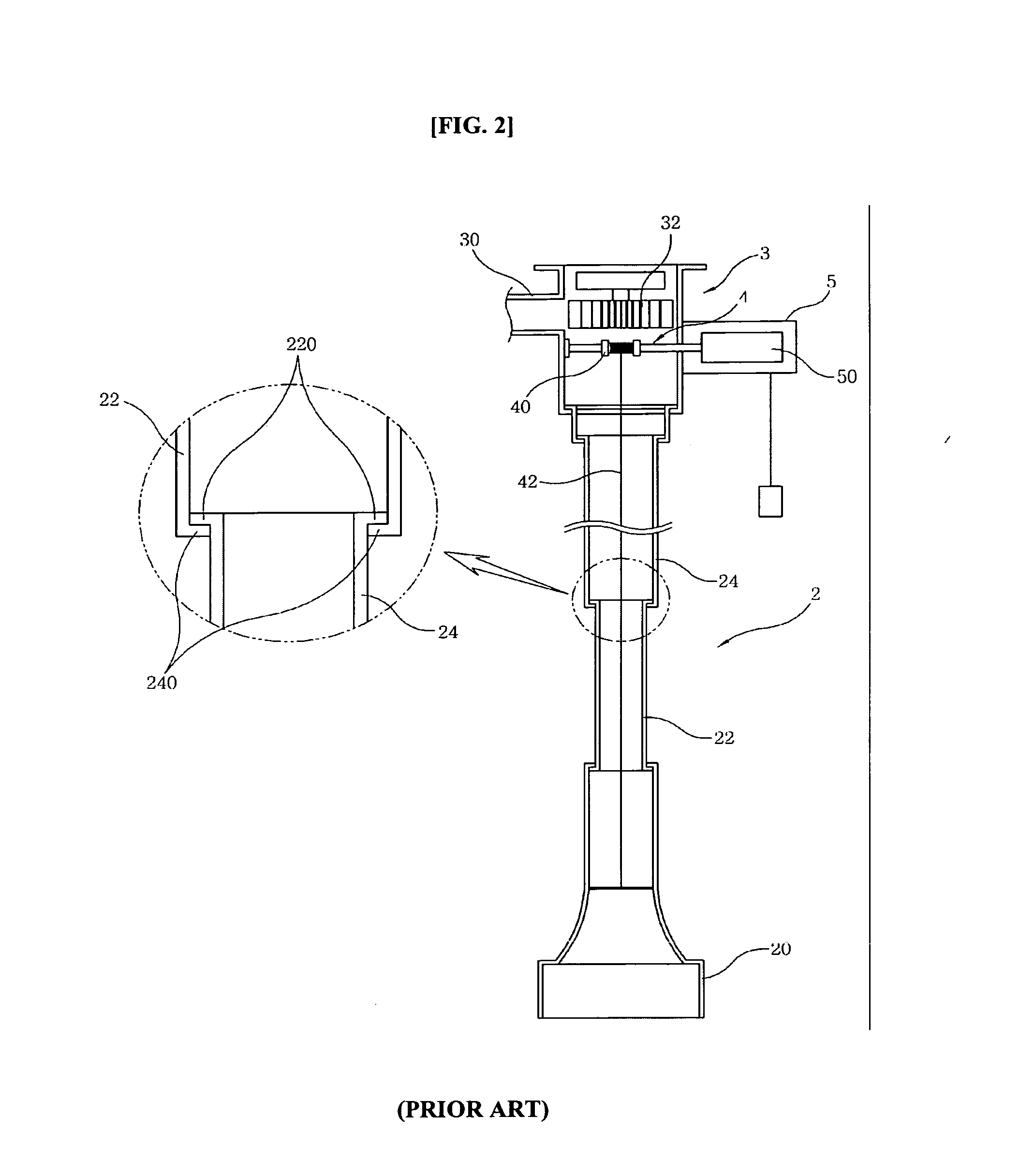
However, in the case of the conventional exhauster for the roaster as described above, the stationary tube 24 connected to the hood main body 3 cannot be completely embedded in the hood main body 3.
Accordingly, gaps may be formed between the connection portion of the respective tubes, and the polluted materials which are put through the hood tube 2 may flow and leak via the joint portions to then be unable to be clean.

Method used


Image

  • Exhauster for roaster
  • Exhauster for roaster
  • Exhauster for roaster

Examples


Embodiment Construction

[0036] An exhauster for a roaster according to a preferred embodiment of the present invention will be described with reference to the accompanying drawings.

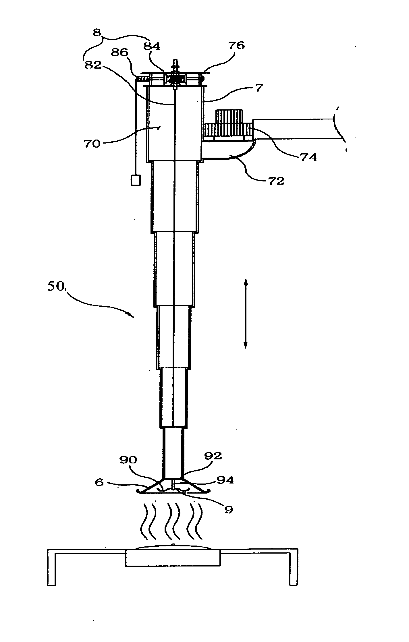
[0037]FIG. 3. is a side sectional view showing an overall configuration of an exhauster for a roaster according to the present invention. As shown in FIG. 3, the exhauster for a roaster according to the present invention includes a hood body 7 at the side of which a fan 74 is equipped, a hood tube 50 which is combined in the lower portion of the hood body 7, and an elevating apparatus 8 elevating the hood tube 50.

[0038] First, the hood tube 50 is a suction tube which inhales the smoke and smell generated through a roaster in which a plurality of pipes are telescopically combined so as to be folded in a multi-stage. A hood 6 having an extrinsic expansion section is connected at the lower end of the pipe positioned at the lowest bottom in order to collect the smoke and smell which are generated when burning the meat.

[0039] Here...


PUM


Abstract

Provided is an exhauster for a roaster which can exhaust the smell and the smoke which are generated when the meat is burnt in a restaurant, etc., to the outside of the restaurant. The exhauster includes: a hood tube in which a plurality of hood pipes can be combined so as to be folded in a multi-stage, and packings are applied to connection portions of the respective pipes to thereby prevent a gap from being formed between the connected hood pipes and the leak of the foreign matters from occurring; a hood main body having a space portion of a vertical direction length so that the contracted hood tube is completely inserted when the hood tube has been completely contracted, an exhaust tube having a fan which is installed at an axial portion in communication with the hood main body, and a bracket which is installed at the upper end thereof to then be fixed on the ceiling; and an elevating apparatus which is provided on the bottom of the bracket of the hood main body, including a winding reel around which a lifting chain is wound and a motor driving the winding reel, to thereby extend or contract the hood tube, in which the elevating apparatus is driven by a wireless remote controller.

Description

CROSS-REFERENCE TO RELATED PATENT APPLICATION [0001] This application claims the benefit of Korean Utility Model Registration Application No. 20-2005-0029123, filed on Oct. 12, 2005, in the Korean Intellectual Property Office, the disclosure of which is incorporated herein in its entirety by reference. BACKGROUND OF THE INVENTION [0002] 1. Field of the Invention [0003] The present invention relates to an exhauster for a roaster which can exhaust the smell and the smoke which are generated when the meat is burnt in a restaurant, etc., to the outside of the restaurant, and more particularly, to an exhauster for a roaster, in which a plurality of hood pipes can be telescopically combined to form a hood tube in a multi-stage, and thus the hood tube is completely inserted into a hood main body, and since the exhauster including the hood tube is completely buried and installed into a ceiling slab, to then be hidden, the whole aesthetics in the restaurant are prevented from being degraded ...

Claims


Application Information

Patent Timeline
IPC IPC(8): F24C15/20
CPCF24C15/2085A47J37/00A47J37/06
Inventor SHIN, HYEON-GU
Owner SHIN HYEON GU
Learn More