Heat shrunk double wall, self-insulating, lightweight duct

a double wall, lightweight technology, applied in the direction of flexible pipes, pipe protection by thermal insulation, pipe protection, etc., can solve the problems of time-consuming manufacture and installation, undesirable weight of insulation blankets, and undesirable weight of insulation blankets, and achieve high flow rates and high temperatures

Inactive Publication Date: 2007-04-12
ARROWHEAD PROD
View PDF24 Cites 21 Cited by
  • Summary
  • Abstract
  • Description
  • Claims
  • Application Information

AI Technical Summary

Benefits of technology

[0013] Briefly and in general terms, the present invention is directed to a lightweight duct used to transfer fluid to specified areas in a common carrier. The duct includes tubular walls that form an annulus to trap a thermally insulating gas therein. The walls that form the duct may be made from polymeric materials and may be reinforced by a helical cord. In one preferred embodiment, the material used to form the walls is a polymide, such as Kapton® or polyetherether ketone film. The outer tube, formed of material with a memory, is slid over the inner tube and heated to be shrunk thereon. We have discovered that by employing an extremely thin film of PEEK or a similar polymer and reinforcing the inner tube, our duct can withstand the high temperatures and high flow rates associated with even exhaust gas bypassed from jet engines. The film used to form the inner wall of the duct may be as thin as 0.0005 inches. A film used to form the outer wall may be as thin as 0.00025 inches. By heating the outer tube to a selected degree it can be shrunk radially onto the reinforced inner tube to the point where it traps the reinforcing cord in place and diminishes the annulus between the inner and outer wall to a selected radial thickness necessary to present the thermal barrier desired for the particular application.

Problems solved by technology

Our particular challenging task is the flow of hot air from jet engine bypasses.
The problem with the ducts of the present is the weight associated with the insulation blankets.
The weight associated with the insulation blankets are undesirable and can be thought of as a parasitic factor in the overall design of the ECS and the common carrier.
Another problem with ducts that use insulation blankets is the time consuming effort of manufacture and installation.
This presents a two-fold problem.
The second problem stems from efforts to conceal the ducts and their structures with the insulation blankets.
By covering the ducts, the insulation blankets make it difficult not only to visually inspect ducts, but also to spot any damage or flaws in the ducts.
This slows the process for identifying ducts in need of repair or replacement since insulation blankets must be removed and replaced whenever a duct is suspected of being damaged.
Such ducts, while having utility for general ducting work, suffer the shortcoming that the rubber material does not meet the specifications for aerospace applications and are typically relatively heavy and do not incorporate effective thermal barriers.
Again devices of this type again add unwanted weight.
Such vacuum jacket construction is not generally acceptable for use even in aerospace vehicles as the dual wall metal construction adds significantly to the overall weight and it would be prohibitively expensive to construct the ducting to maintain an effective vacuum and to hold that vacuum.

Method used


Image

  • Heat shrunk double wall, self-insulating, lightweight duct
  • Heat shrunk double wall, self-insulating, lightweight duct
  • Heat shrunk double wall, self-insulating, lightweight duct

Examples


Embodiment Construction

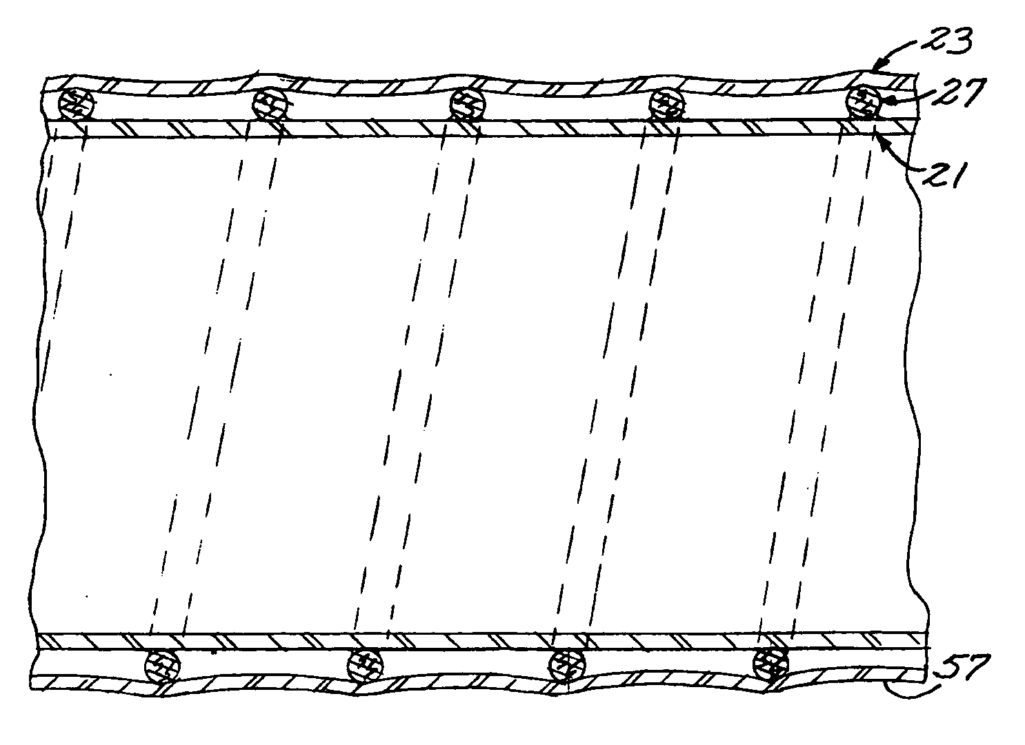
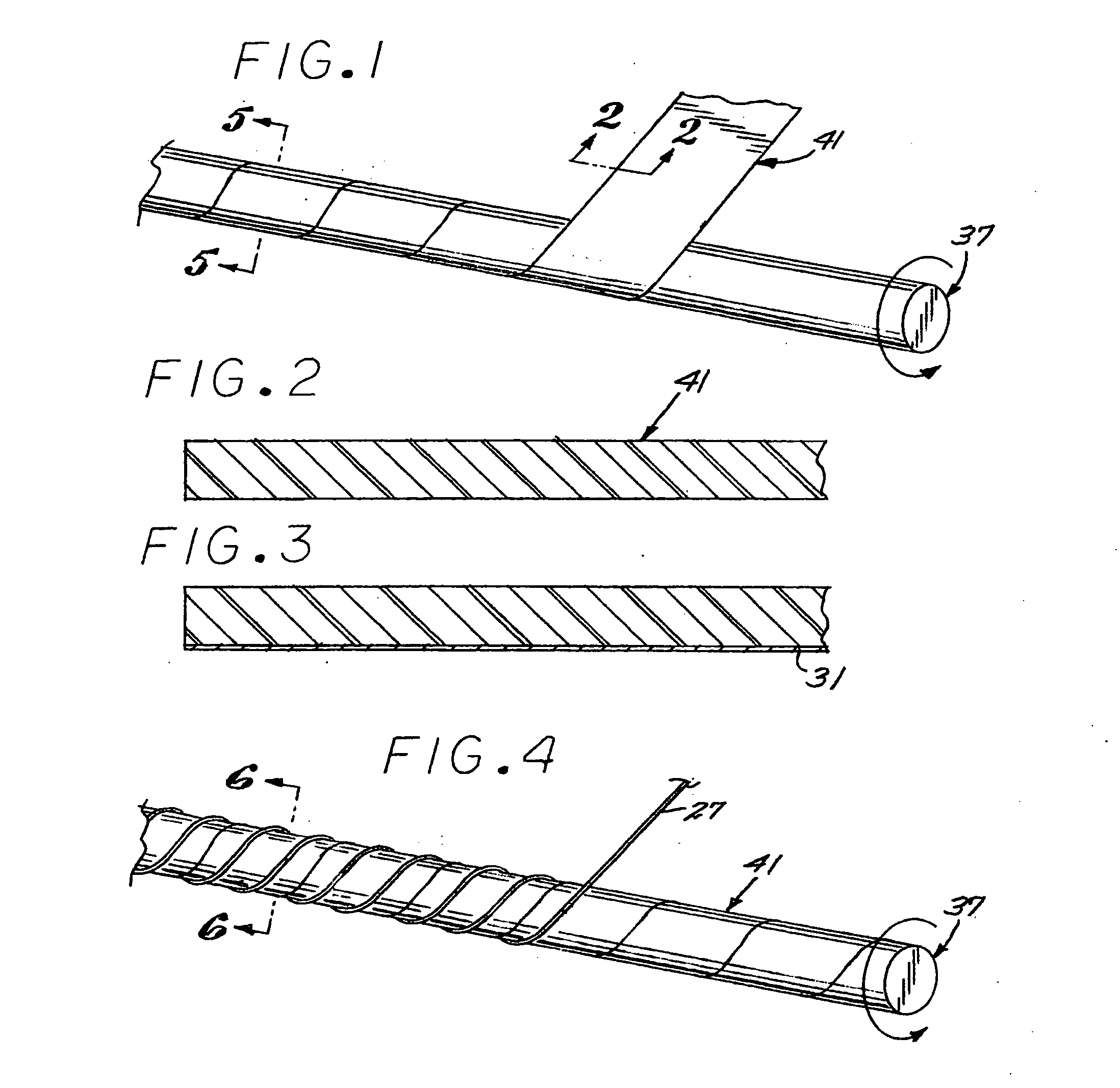
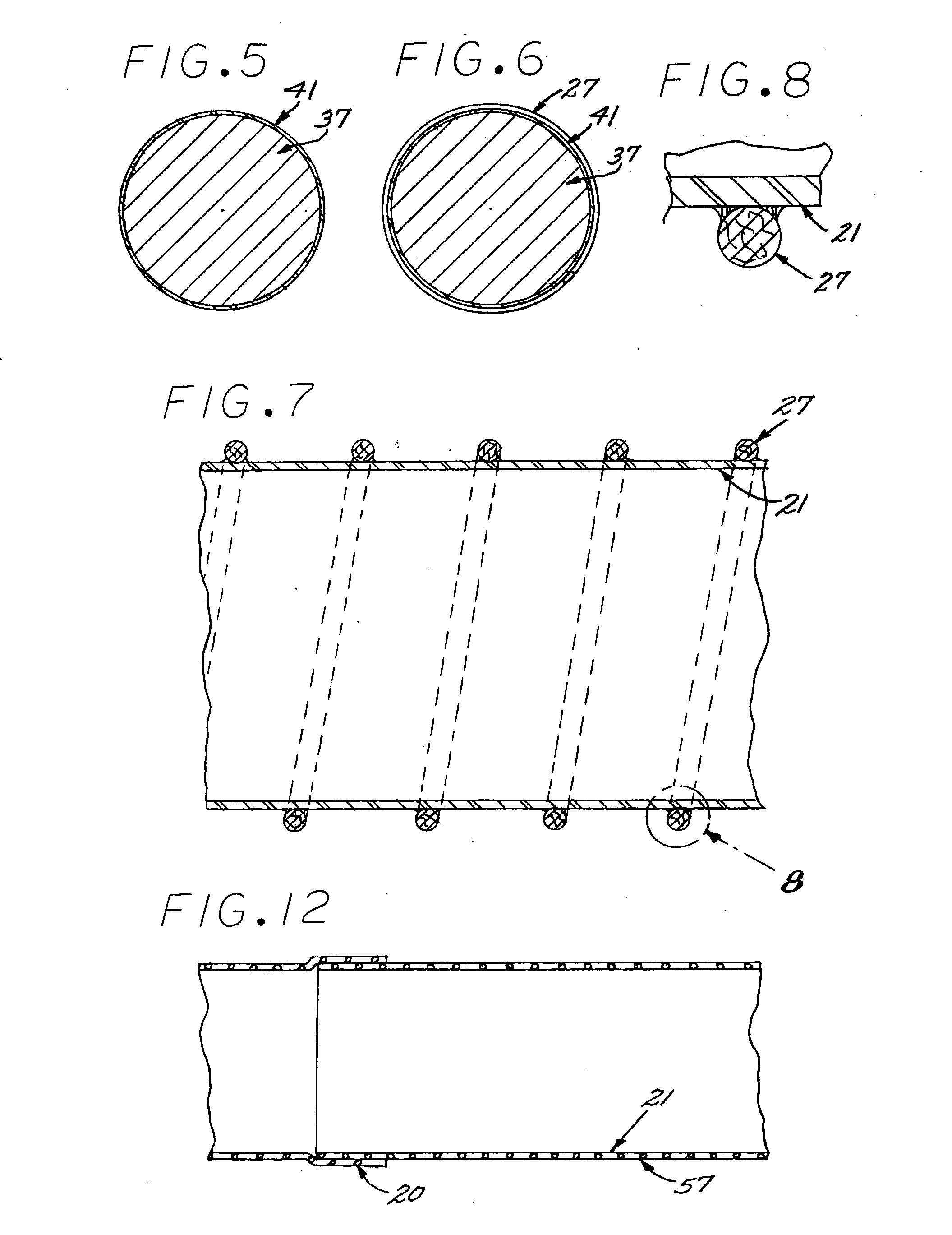
[0029] The lightweight self-insulated duct device of the present invention includes, concentric inner and outer tubes 21 and 23 constructed of an ultra thin flame resistant polymer such as polyetherether keytone. The walls cooperate to form therebetween an annulus 25 housing a helical reinforcing element, generally designated 27, which may also be constructed as a polymer such as polyethersulfone and, in the preferred embodiment, also serves as a radial spacer for establishing the radial thickness of the annulus 25. The outer tube 23 is formed by stretching it to a diameter substantially larger than that of the wrapped inner tube so it can be conveniently telescoped there over. Heat may then be applied to shrink it into position as shown in FIG. 10 to constrain the cord and inner tube while trapping air in the annulus 25.

[0030] Commercial aircraft have typically utilized flexible and rigid ducts of varying diameters and configuration for circulating air within cabin and for cooling...


PUM


Abstract

A dual wall duct constructed of heat resistant polymer, a reinforcing cord interposed between the inner and outer tube and the outer tube heat shrunk on the inner to form an annulus for entrapment for thermally insulated gas such as air.

Description

FIELD OF THE INVENTION [0001] The present invention relates to a very lightweight duct for circulating air to or from specified locations within a common carrier. BACKGROUND OF THE INVENTION [0002] 1. Description of the Prior Art [0003] Common carriers such as aircraft, automobiles, naval vessels and trains require the circulation of air and gases within specific areas for controlling the environment and the exhausting heat exhaust gases. To accomplish such circulation, many vehicles use ducts to carry and circulate the gas from one area to another. The use of ducts to circulate gas is commonly known as an environmental control system (“ECS”). Our particular challenging task is the flow of hot air from jet engine bypasses. Using duct systems for this purpose can be very convenient yet has it own drawbacks. [0004] It has long been recognized that lightweight ducting is desirable for aircraft usage. In recognition of this problem it has proposed to construct dual wall metallic ducting...

Claims


Application Information

Patent Timeline
Patent Type & Authority Applications(United States)
IPC IPC(8): F16L11/00
CPCF16L11/081F16L59/06F16L59/143
Inventor TOMERLIN, REGLARNER, DAVID S.JUN, KATHY
Owner ARROWHEAD PROD
Why Eureka
Try Eureka