Device for moving at least one moveable element in a gas turbine

a technology of moving elements and gas turbines, which is applied in the direction of mechanical control devices, process and machine control, instruments, etc., can solve the problems of wear of the parts of the articulation joints, and achieve the effect of reducing the tension in the link member, facilitating replacement of parts, and reducing the lever distance from the annular member to the link member

Active Publication Date: 2007-04-12
GKN AEROSPACE SWEDEN AB
View PDF6 Cites 4 Cited by
  • Summary
  • Abstract
  • Description
  • Claims
  • Application Information

AI Technical Summary

Benefits of technology

[0010] According to a further embodiment of the invention, the link member extends between the first articulation joint and a second articulation joint adapted to be connected to the annular member and that the support surface is positioned between the first articulation joint and the second articulation joint. A lever distance from the annular member to the link member is reduced and the tensions in the link member are thereby also reduced.
[0011] According to a further embodiment of the invention, the device comprises means for releasably securing the support member to a stationary casing. By manufacturing the support member and the casing in two separate pieces, the replacement of parts is facilitated. Further, conditions are created for reducing wear significantly in that good tolerance may be achieved between the glide surfaces of the link member and the support member.

Problems solved by technology

A large amount of the torque from the annular member was transmitted via the link member to an articulation joint during operation, which led to wear of the parts of the articulation joint.

Method used


Image

  • Device for moving at least one moveable element in a gas turbine
  • Device for moving at least one moveable element in a gas turbine
  • Device for moving at least one moveable element in a gas turbine

Examples


Embodiment Construction

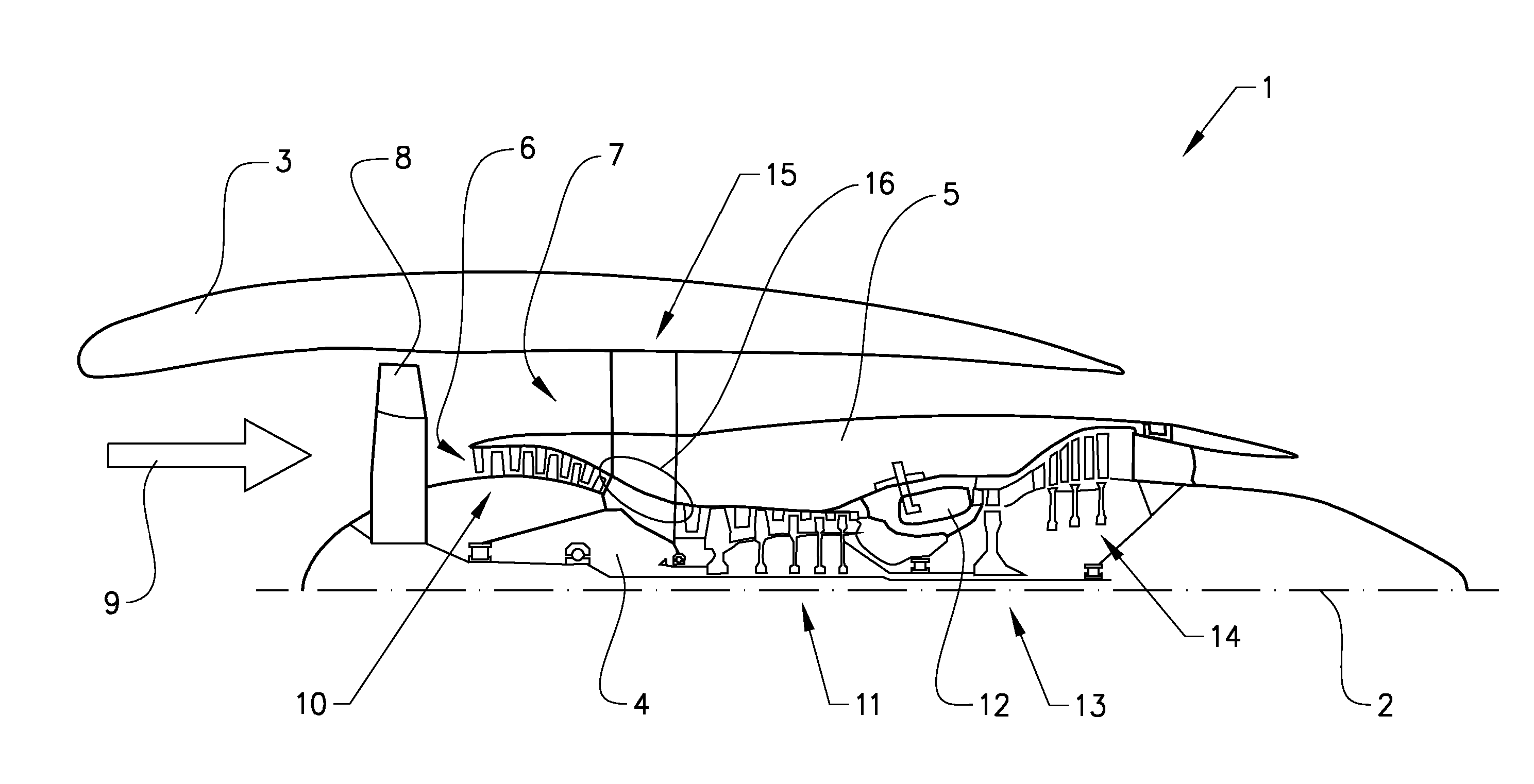
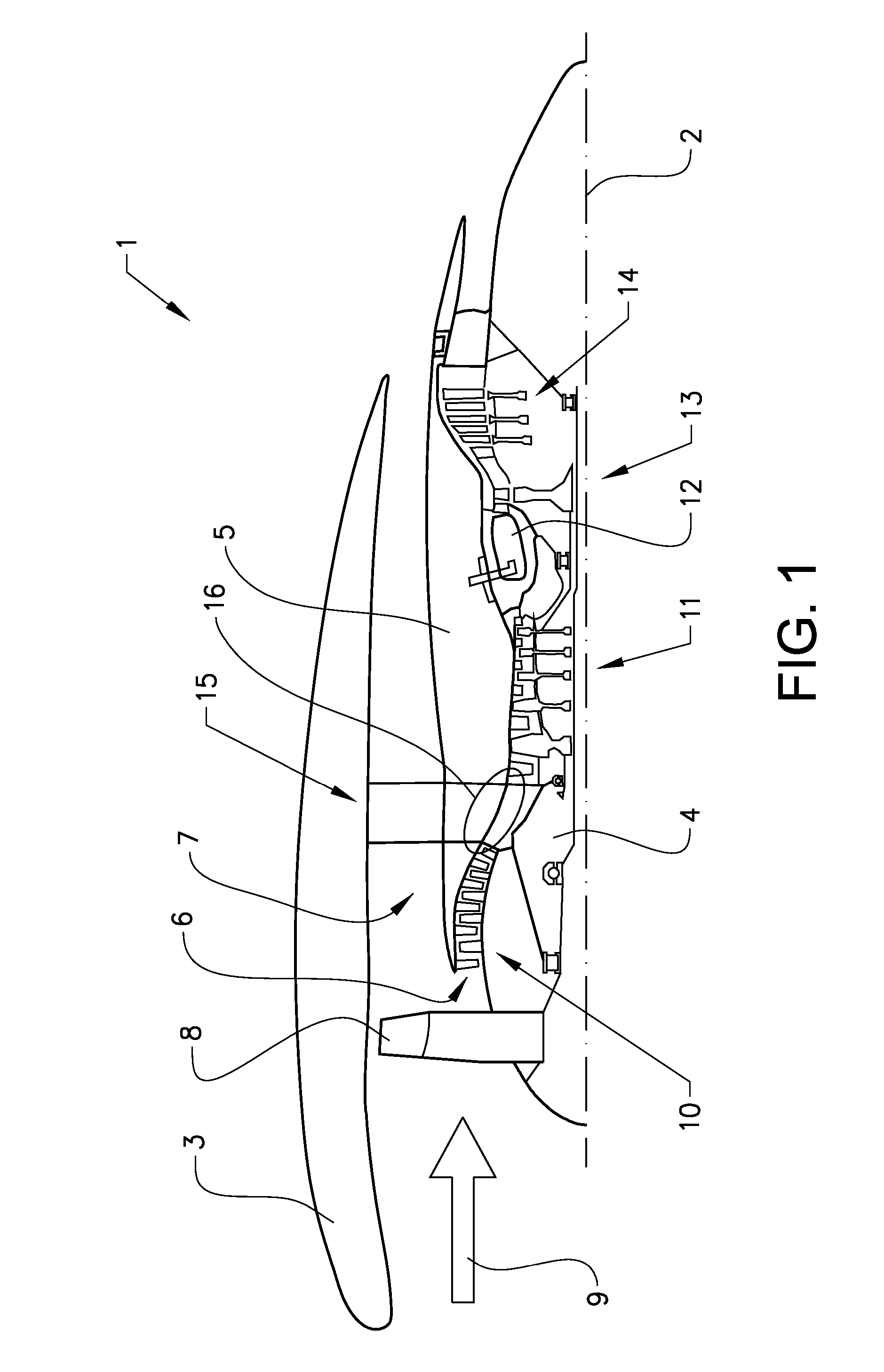
[0025] The invention is described below in the form of a turbofan gas turbine aircraft engine 1, which in FIG. 1 is circumscribed about an engine longitudinal central axis 2. The engine 1 comprises an outer casing 3, or nacelle, an inner casing 4, and an intermediate casing 5, which is concentric to the first two casings and divides the gap between them into an inner primary gas duct 6 for the compression of air and a secondary duct 7 in which the engine bypass air flows. Thus, each of the gas ducts 6,7 is annular in a cross section perpendicular to the engine longitudinal central axis 2.

[0026] The engine 1 comprises a fan 8 which receives ambient air 9, a booster or low pressure compressor (LPC) 10 and a high pressure compressor (HPC) 11 arranged in the primary gas duct 6, a combustor 12 which mixes fuel with the air pressurized by the high pressure compressor 11 for generating combustion gases which flow downstream through a high pressure turbine (HPT) 13 and a low pressure turbi...


PUM


Abstract

The invention relates to a device (20) for moving at least one moveable element (19) in a gas turbine engine (1) between a first and a second position. The device includes a linkage (21) that connects a pivotable annular member (18) with the moveable element (19) in such a way that the movement of the moveable element (19) between the two positions is accomplished when the annular member (18) is pivoted. The linkage (21) has a link member (22) connected to the moveable element (19) via a first articulation joint (23). The device also has a support member (24) that supports the link member (22) at a distance from the first articulation joint.

Description

FIELD OF THE INVENTION [0001] The present invention relates to a device for moving at least one moveable element in a gas turbine between a first and a second position, the device comprises a linkage adapted for connecting a pivotable annular member with said moveable element in such a way that the movement of the moveable element between the two positions is accomplished when said annular member is pivoted, wherein the linkage comprises a link member connected to the moveable element via a first articulation joint. BACKGROUND OF THE INVENTION [0002] The present disclosure is primarily directed toward applications in an aircraft jet engine. The device may be arranged for controlling air bleed. In known aircraft jet engines, a bleed passage extends between the primary gas duct and the secondary gas duct in order to bleed air from the primary gas duct to the secondary gas duct. In certain operational conditions, compressed air is bled from the primary gas duct via the bleed passage an...

Claims


Application Information

Patent Timeline
Patent Type & Authority Applications(United States)
IPC IPC(8): B64C3/50
CPCF01D17/10F01D17/105F02C9/18Y10T74/18888F05D2260/50Y10T74/20F02K3/075F04D27/0215F04D27/023
Inventor ARONSSON, EGONBILLETT, MIKE
Owner GKN AEROSPACE SWEDEN AB
Why Eureka
Try Eureka