Plasma display panel

a technology of display panel and plasma, which is applied in the direction of discharge tube/lamp details, discharge tube luminescnet screen, address electrode, etc., can solve the problems of significant power consumption caused by address discharge, and achieve the effect of shortening the distance between electrodes used and improving luminous efficiency

Inactive Publication Date: 2007-04-12
SAMSUNG SDI CO LTD
View PDF26 Cites 1 Cited by
  • Summary
  • Abstract
  • Description
  • Claims
  • Application Information

AI Technical Summary

Benefits of technology

[0010] It is also an object of the present invention to provide a design for a PDP that shortens the distance between electrodes used during the address discharge.
[0011] The pr

Problems solved by technology

As a result, power consumption caused as a resu

Method used


Image

  • Plasma display panel
  • Plasma display panel
  • Plasma display panel

Examples


Embodiment Construction

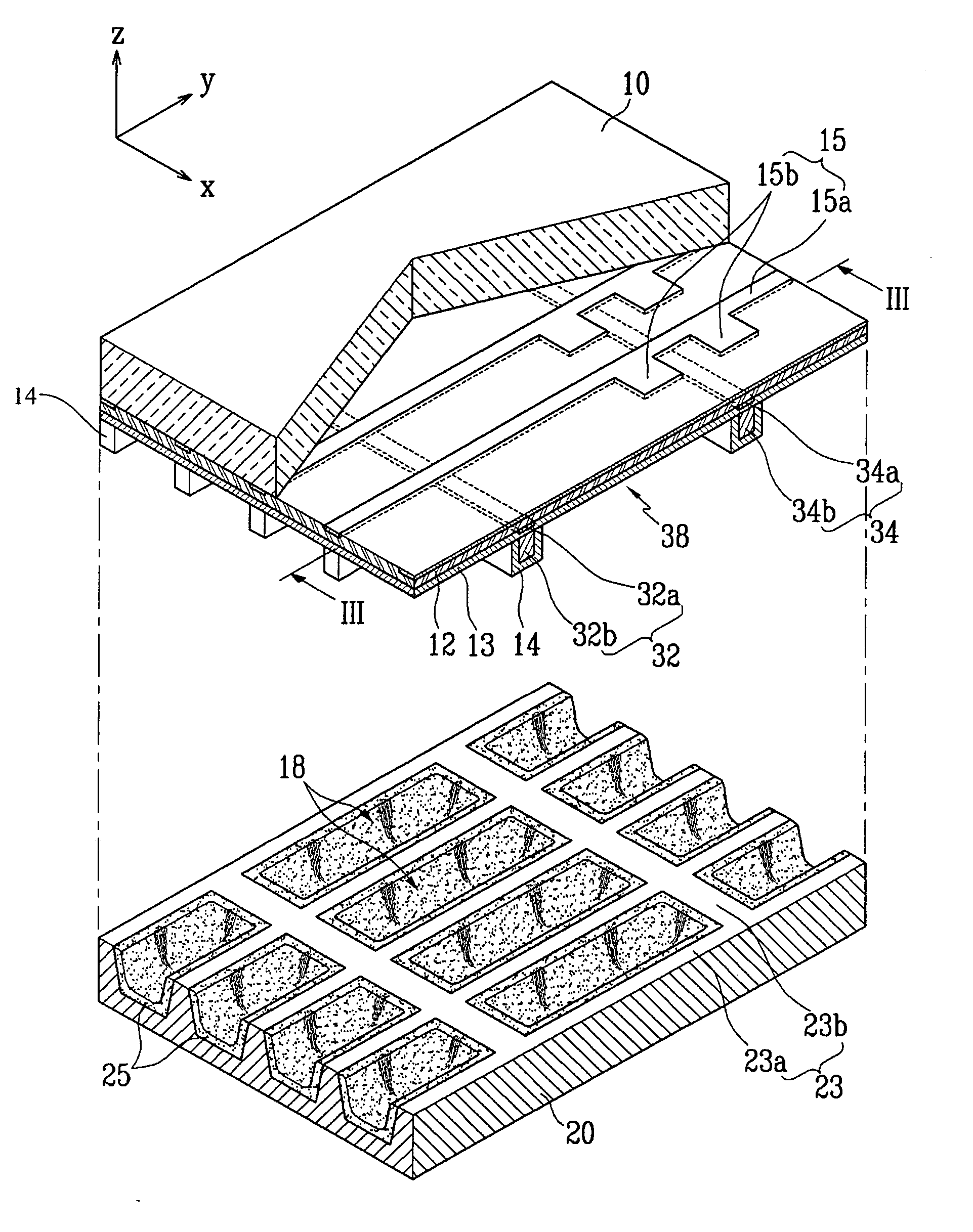
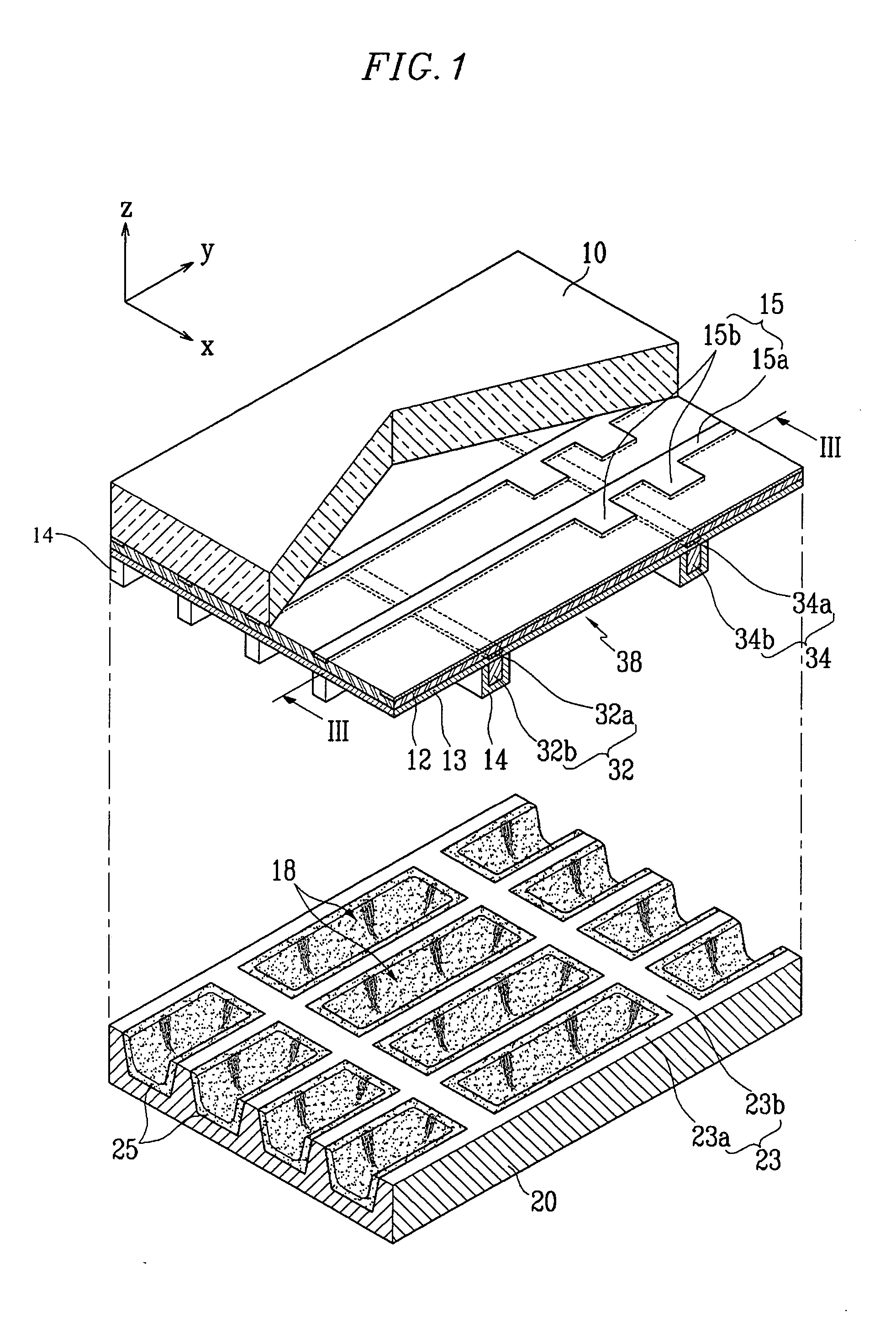
[0023] Turning now to the figures, FIG. 1 is an exploded perspective view illustrating a part of a PDP according to the first embodiment of the present invention. As illustrated, the PDP according to the first embodiment includes a first substrate 10 (hereinafter referred to as “front substrate”) and a second substrate 20 (hereinafter referred to as “rear substrate”) which face each other in parallel while having a distance between them.

[0024] A plurality of discharge cells 18 are partitioned between the front substrate 10 and the rear substrate 20. The discharge cells 18 are particularly partitioned by barrier ribs 23, which are formed by etching the rear substrate 20. In addition, although not illustrated, the discharge cells can be partitioned by barrier ribs that are additionally formed on the rear substrate.

[0025] Each of the barrier ribs 23 includes a first barrier rib member 23a and a second barrier rib member 23b. The first barrier rib member 23a extends in a first directi...


PUM


Abstract

A plasma display panel (PDP) with improved luminous efficiency by having a low discharge current. The PDP includes a first substrate, a second substrate facing the first substrate with a distance therebetween, multiple discharge cells located between the first substrate and the second substrate, address electrodes extending in a first direction on the first substrate and corresponding to the discharge cells, and first and second electrodes electrically isolated from the address electrodes and extending in a second direction crossing the first direction. Each of the address electrodes includes an elongated portion and a pair of protruding portions. Each of the first electrodes includes a first elongated portion and a first floating portion. Each of the second electrodes includes a second elongated portion and a second floating portion.

Description

CLAIM OF PRIORITY [0001] This application makes reference to, incorporates the same herein, and claims all benefits accruing under 35 U.S.C. §119 from an application earlier filed in the Korean Intellectual Property Office on Oct. 11, 2005 and there duly assigned Serial No. 10-2005-0095370. BACKGROUND OF THE INVENTION [0002] 1. Field of the Invention [0003] The present invention relates to a plasma display panel (PDP). More particularly, the present invention relates to a PDP with improved luminous efficiency by limiting an amount of discharge current. [0004] 2. Description of the Related Art [0005] Generally, a PDP excites phosphors using vacuum ultraviolet (VUV) rays illuminated from a plasma generated from a gas discharge, and expresses images using visible light of red, green, and blue colors emitted from the phosphors. A PDP can have a very wide screen of larger than 60 inches, while having a thickness of only about 10 cm. Also, a PDP is an emissive display like a cathode ray t...

Claims


Application Information

Patent Timeline
IPC IPC(8): H01J1/62H01J11/14H01J11/26H01J11/30H01J11/38
CPCH01J11/14H01J11/26H01J11/30H01J11/38H01J2211/245
Inventor KIM, JEONG-NAMPAKR, HYOUNG-BIN
Owner SAMSUNG SDI CO LTD
Why Eureka
Try Eureka