Circuit system and method for coupling a circuit module to or for decoupling the same from a main bus

a circuit module and circuit technology, applied in the field of circuit systems, can solve the problems of/or the number of connectable memory modules, signal distortion, and limiting the overall bandwidth of the bus, so as to achieve no additional cost, no significant capacitance, and low complexity of additional circuitry

Inactive Publication Date: 2007-04-12
INFINEON TECH AG
View PDF16 Cites 10 Cited by
  • Summary
  • Abstract
  • Description
  • Claims
  • Application Information

AI Technical Summary

Benefits of technology

[0012] It is an advantage of the present invention, that memory modules can be coupled to a main bus or decoupled from the same cost-efficiently, since only one additional element, for example a throttle as a magnetic switch, may be applied for switching. It is another advantage of the present invention that the inventive concept prevents occurring of transient pulses while switching without additional costs, since the curve describing the dependence of the conductance from the currents across the magnetic switch always is differentiable.
[0013] It is a further advantage of the present invention that a complexity of an additional circuitry is low since coupling and decoupling procedures are substantially controlled by a current across the switch.
[0014] It is a further advantage of the present invention that a DC drop or a voltage shift across the switch, both occurring in the case of diode switches, does not occur. Furthermore, no significant capacitance is added, like is the case when MOSFET switches are used. Additionally, the switching state is self-controllable, so that the switch disconnects a signal as the corresponding device changes its state towards a non-conductive (Z) state. The inventive switches can be also integrated into the connectors or boards.

Problems solved by technology

In multi-drop buses (for example a data bus of a computer memory), data rate is often limited by a large number of loads, for example receiver or transmitter input capacitances connected to the bus.
Thus, parasitic parameters of non-active modules cause signal distortions and restrict the overall bandwidth of the bus and / or the number of connectable memory modules.
These stubs cause impedance violations and, therefore, reflections distorting signal shapes.
Thus, the data rate in the data bus of such memory systems including more than one circuit module is restricted due to the influence of the parasitic parameters of the non-active modules.
This approach is, however, quite expensive.
This approach, however, suffers from the parasitic influence caused by the characteristics of the switches.
In addition, transient impulses generated by switching may occur and couple to the memory bus, so that further signal disturbances may result.
This concept suffers from increased system's complexity and increased costs.

Method used


Image

  • Circuit system and method for coupling a circuit module to or for decoupling the same from a main bus
  • Circuit system and method for coupling a circuit module to or for decoupling the same from a main bus
  • Circuit system and method for coupling a circuit module to or for decoupling the same from a main bus

Examples


Embodiment Construction

[0024] The making and using of the presently preferred embodiments are discussed in detail below. It should be appreciated, however, that the present invention provides many applicable inventive concepts that can be embodied in a wide variety of specific contexts. The specific embodiments discussed are merely illustrative of specific ways to make and use the invention, and do not limit the scope of the invention.

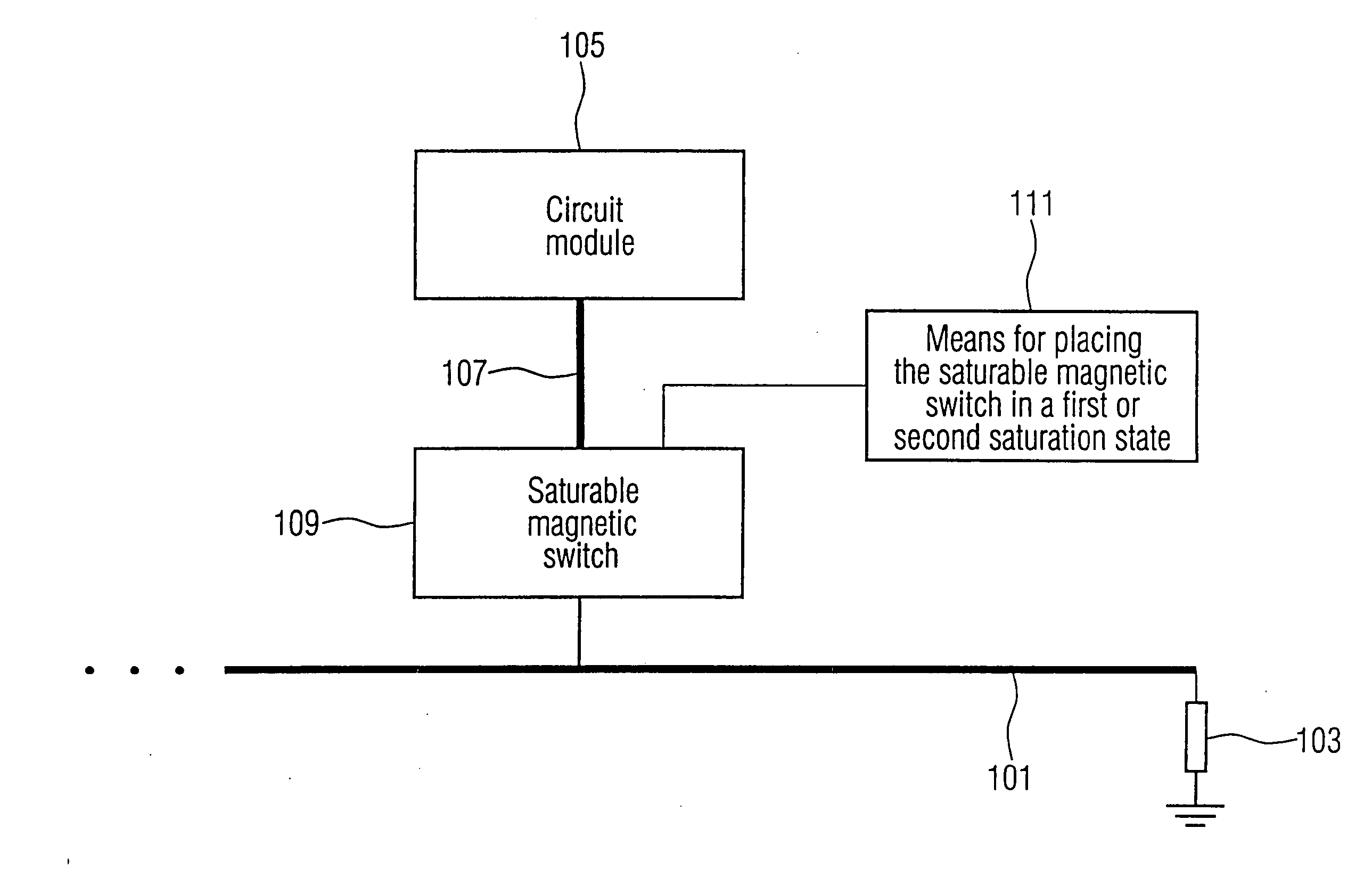
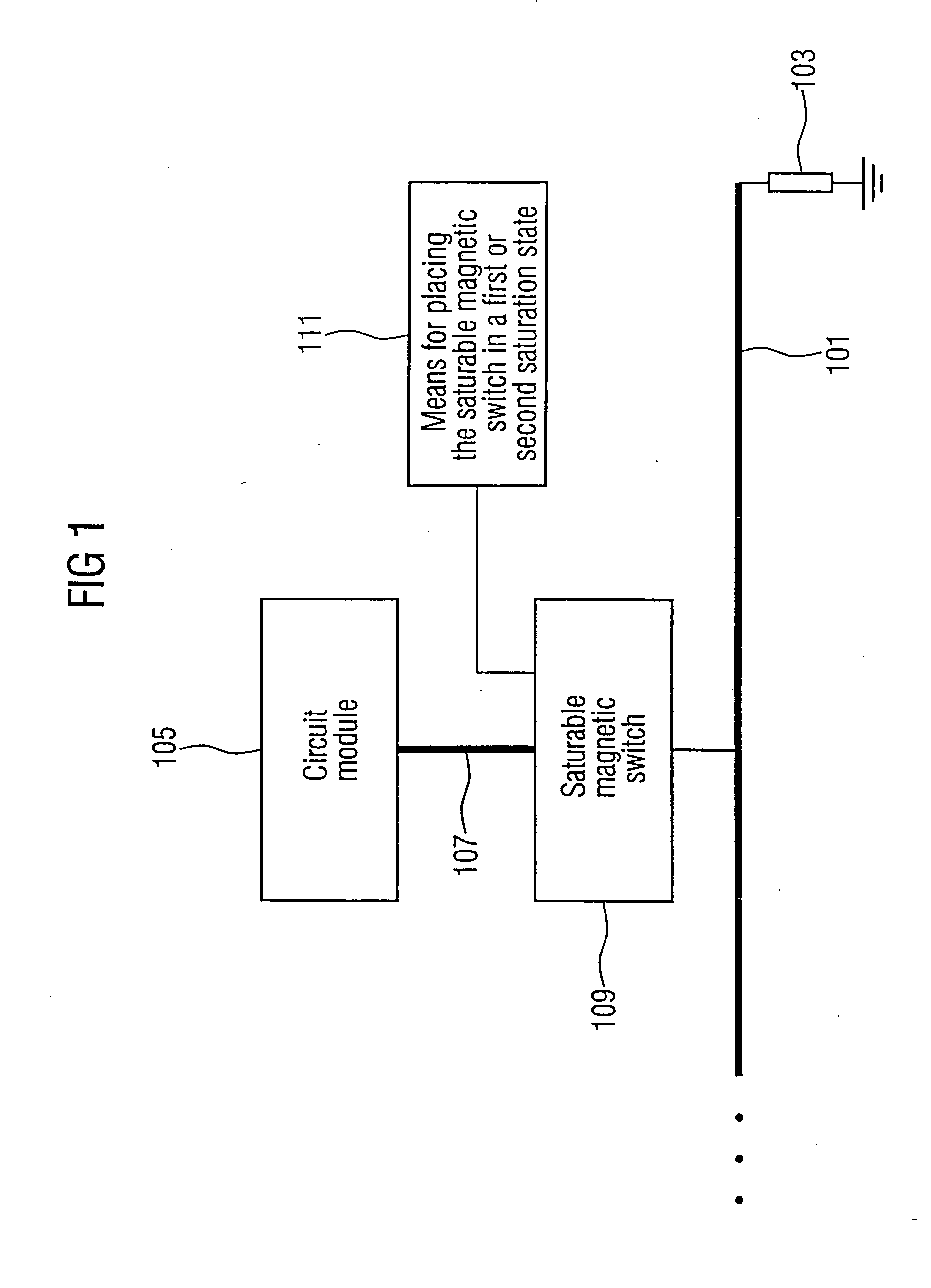
[0025] The circuit system shown in FIG. 1 comprises a main bus 101 terminated by a resistor 103 connected between the main bus 101 and ground. The circuit system shown in FIG. 1 further comprises a circuit module 105 connected to a sub-bus 107, which may be a transmission line. The sub-bus 107 is coupled by a saturable magnetic switch 109 to the main bus 101. Furthermore, means 111 for placing the saturable magnetic switch in a first or second saturation state is coupled to the saturable magnetic switch 109.

[0026] In the following, the functionality of the circuit system s...


PUM

PropertyMeasurementUnit
lengthaaaaaaaaaa
lengthaaaaaaaaaa
lengthaaaaaaaaaa

Abstract

A circuit system has a main bus, a circuit module connected to a sub-bus, a saturable magnetic switch connected between the sub-bus and the main bus, wherein the saturable magnetic switch has a first inductance in a first saturation state and a second inductance in a second saturation state, the first inductance being lower than the second inductance, a unit for placing the magnetic switch in the first saturation state for coupling the sub-bus to the main bus, or for placing saturable magnetic switch in the second saturation state for decoupling the sub-bus from the main bus.

Description

[0001] This application is a continuation of co-pending International Application No. PCT / EP2004 / 007932, filed Jul. 15, 2004, which designated the United States and was published in English, and which is based on European Patent Application No. EP03019788.3, filed Aug. 29, 2003, both of which applications are incorporated herein by reference.TECHNICAL FIELD [0002] The present invention relates to a circuit system comprising a circuit module to be coupled to or to be decoupled from a main bus. In particular, the circuit system can be a memory system, the circuit module can be a memory module and the main bus can be a memory bus. BACKGROUND [0003] In order to read data from a circuit module or to write data to the memory module, a main bus can be provided for accessing the memory module. Usually, the circuit module is connected to the main bus via a sub-bus. Generally, the memory bus and the sub-bus are formed by a number of transmission lines. The conventional structures of memory sy...

Claims


Application Information

Patent Timeline
Patent Type & Authority Applications(United States)
IPC IPC(8): H01F1/00H01F7/00G11C7/10H03K17/80H03K17/81
CPCG11C7/1048H03K17/80H03K17/81
Inventor KUZMENKA, MAKSIM
Owner INFINEON TECH AG
Why Eureka
Try Eureka