Led backlight unit

a backlight unit and led technology, applied in the field of backlight units, can solve the problems of poor efficiency of outward radiation of high-temperature heat, inability to actively respond to the compactness and light weight demands of electronics products, and inability to meet the compactness and light weight requirements, etc., to achieve the effect of raising heat radiation efficiency

Active Publication Date: 2007-04-12
SAMSUNG ELECTRONICS CO LTD
View PDF1 Cites 13 Cited by
  • Summary
  • Abstract
  • Description
  • Claims
  • Application Information

AI Technical Summary

Benefits of technology

[0022] The present invention has been made to solve the foregoing problems of the prior art and therefore an object of certain embodiments of the present invention is to provide an LED backlight unit capable of radiating heat from a light source to the outside along a simplified path in order to raise heat radiation efficiency.

Problems solved by technology

However, the CRT cannot actively respond to compactness and light weight demands of electronics products because of its own weight and size.
The CRT has certain restrictions in weight and size and thus does not satisfy the compactness and light weight trend of various electronic products.
Then, the efficiency of outwardly radiating high-temperature heat becomes poor in comparison to a case where the heat conducting member 11b directly contacts the metal chassis 16.
This as a result accelerates deterioration of the LED package thereby shortening its lifetime and degrading heat radiating characteristics of the backlight units 10 and 20.
Thus, these problems disadvantageously increase the manufacturing cost of the backlight unit.
Moreover, the MCPCB 12, 22 with the LED 11, 21 mounted thereon is an expensive board having a metal member of excellent heat conductivity, and thus acts as another factor of increasing the manufacturing cost of the backlight unit.

Method used


Image

  • Led backlight unit
  • Led backlight unit
  • Led backlight unit

Examples


second embodiment

[0068]FIG. 6 is a sectional view of an LED backlight unit 100a according to the invention, and FIG. 7 is a detailed view of B part in FIG. 6.

first embodiment

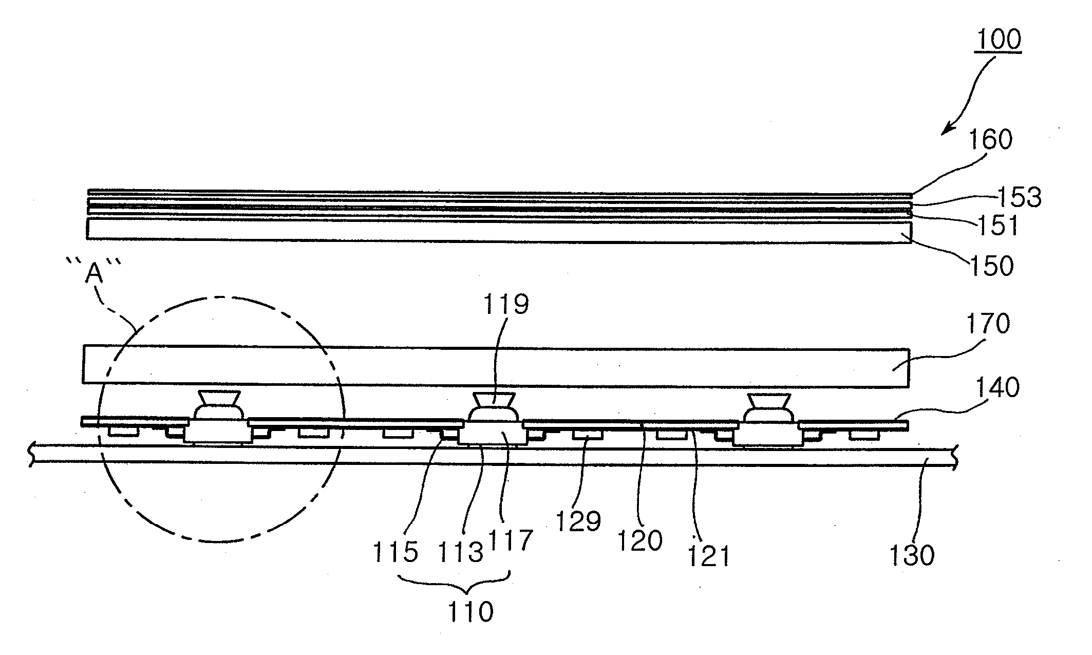
[0069] Referring to FIGS. 6 and 7, the LED backlight unit 100a of the invention includes light sources 110a, a board 120, a metal chassis 130 and a reflector 140, in which the same components are designated with the same reference signs as in the first embodiment and detailed descriptions thereof will be omitted.

[0070] In the LED backlight unit 100a shown in FIGS. 6 and 7, the lead 115a is provided as an electrode terminal electrically connected to the light emitting chip 111 via the wire 111a in which the other end is exposed through an upper surface of the molding 117 to be electrically connected to the circuit pattern 121 formed on the underside of the board 120 so that the light source 110a can be surface-mounted on the board 120.

[0071] In such a case, the electrode terminal or lead 115a of the light source 110a is bonded to the circuit pattern 121 via solder 115b to supply external voltage to the light emitting chip 111.

[0072] In addition, the outside diameter of the molding ...


PUM

PropertyMeasurementUnit
heat conductiveaaaaaaaaaa
lengthaaaaaaaaaa
thicknessaaaaaaaaaa

Abstract

An LED backlight unit includes a light source; a board including a circuit pattern printed on an underside thereof, and having at least one mounting hole perforated therein where the light source is inserted; a metal chassis having an inside surface on which an underside of the light source is mounted, and receiving the board to be arranged in parallel to and with a gap from the metal chassis; and a reflector arranged on a top surface of the board to reflect light generated from the light source. The heat radiating path for transferring heat from the light source to the outside can be more simplified to enhance heat radiation efficiency thereby raising product reliability. The number of whole components can be reduced and the board with the light mounted thereon can be replaced with an inexpensive part thereby saving fabrication cost.

Description

CLAIM OF PRIORITY [0001] This application claims the benefit of Korean Patent Application No. 2005-96173 filed on Oct. 12, 2005, in the Korean Intellectual Property Office, the disclosure of which is incorporated herein by reference. BACKGROUND OF THE INVENTION [0002] 1. Field of the Invention [0003] The present invention relates to a backlight unit incorporating LEDs as a light source. More particularly, the LED backlight unit of the invention is designed to radiate heat more efficiently from the light source to the outside, reduce constitutional parts, and utilize an inexpensive product for a board where the light source is mounted. [0004] 2. Description of the Related Art [0005] A Cathode Ray Tube (CRT) is one of common display devices used in a monitor of a TV, a measuring instrument, an information terminal and the like. However, the CRT cannot actively respond to compactness and light weight demands of electronics products because of its own weight and size. [0006] The CRT has...

Claims


Application Information

Patent Timeline
Patent Type & Authority Applications(United States)
IPC IPC(8): G09F13/04F21S2/00F21V29/00F21Y101/02G02F1/13357H01L33/00H01L33/44H01L33/56H01L33/58H01L33/60H01L33/62H01L33/64
CPCG02F1/133603G02F1/133608G02F2001/133628H05K1/021H05K1/182H05K2201/10106H05K2201/1056H01L2224/48091H01L2924/00014G02F1/133628G02F1/1335
Inventor YUN, HYEONG WONLEE, HYUN HO
Owner SAMSUNG ELECTRONICS CO LTD
Why Eureka
Try Eureka