
Highly efficient isolated AC/DC power conversion technique

a conversion technique and high efficiency technology, applied in the direction of electric variable regulation, process and machine control, instruments, etc., can solve the problems of increasing the complexity of the power converter, increasing the size and cost of the overall circuit, etc., to reduce the power requirements, reduce the circuit size and complexity, and improve efficiency

Active Publication Date: 2007-04-12
TEXAS INSTR INC
View PDF20 Cites 173 Cited by
  • Summary
  • Abstract
  • Description
  • Claims
  • Application Information

AI Technical Summary

Benefits of technology

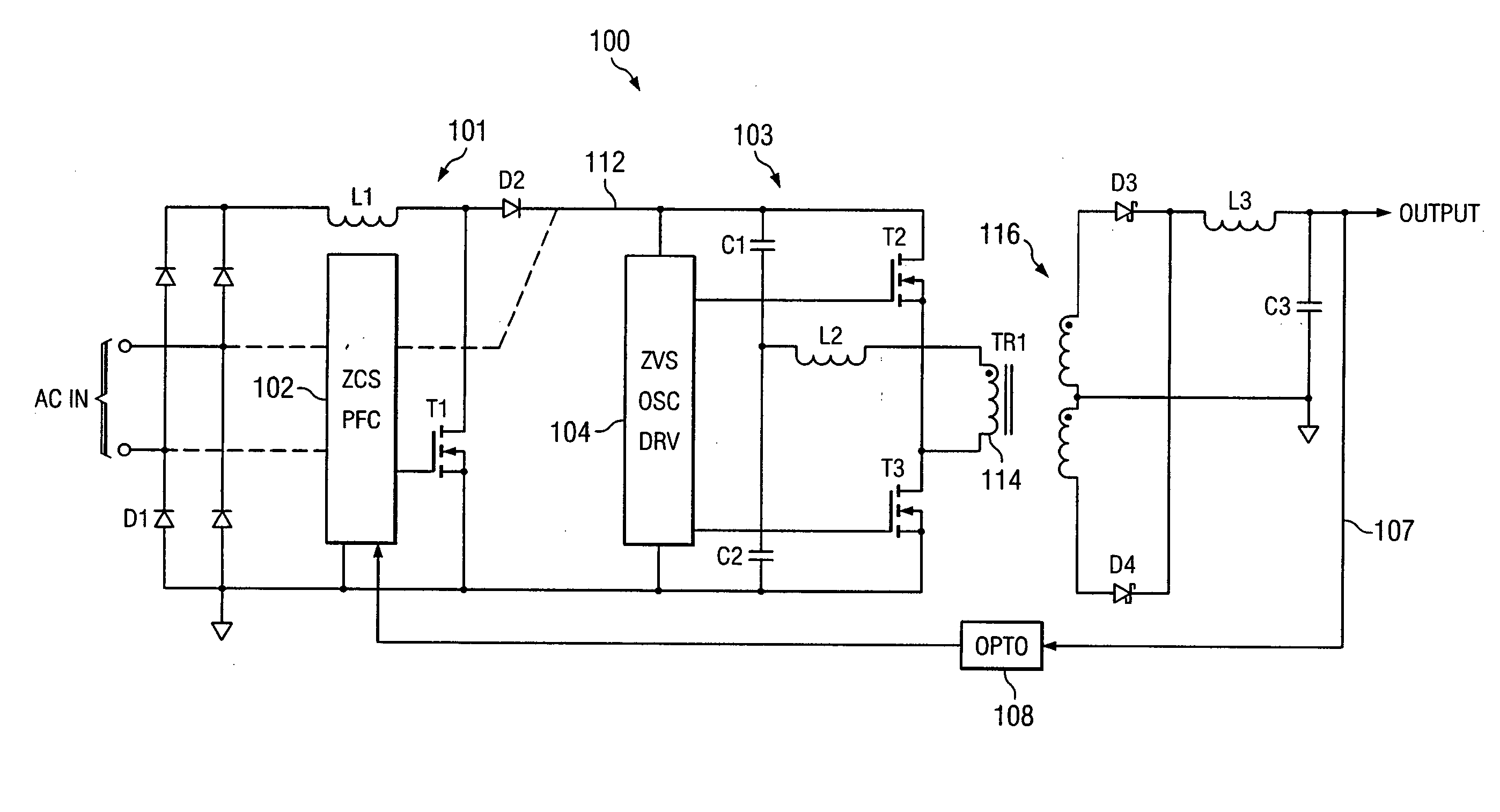
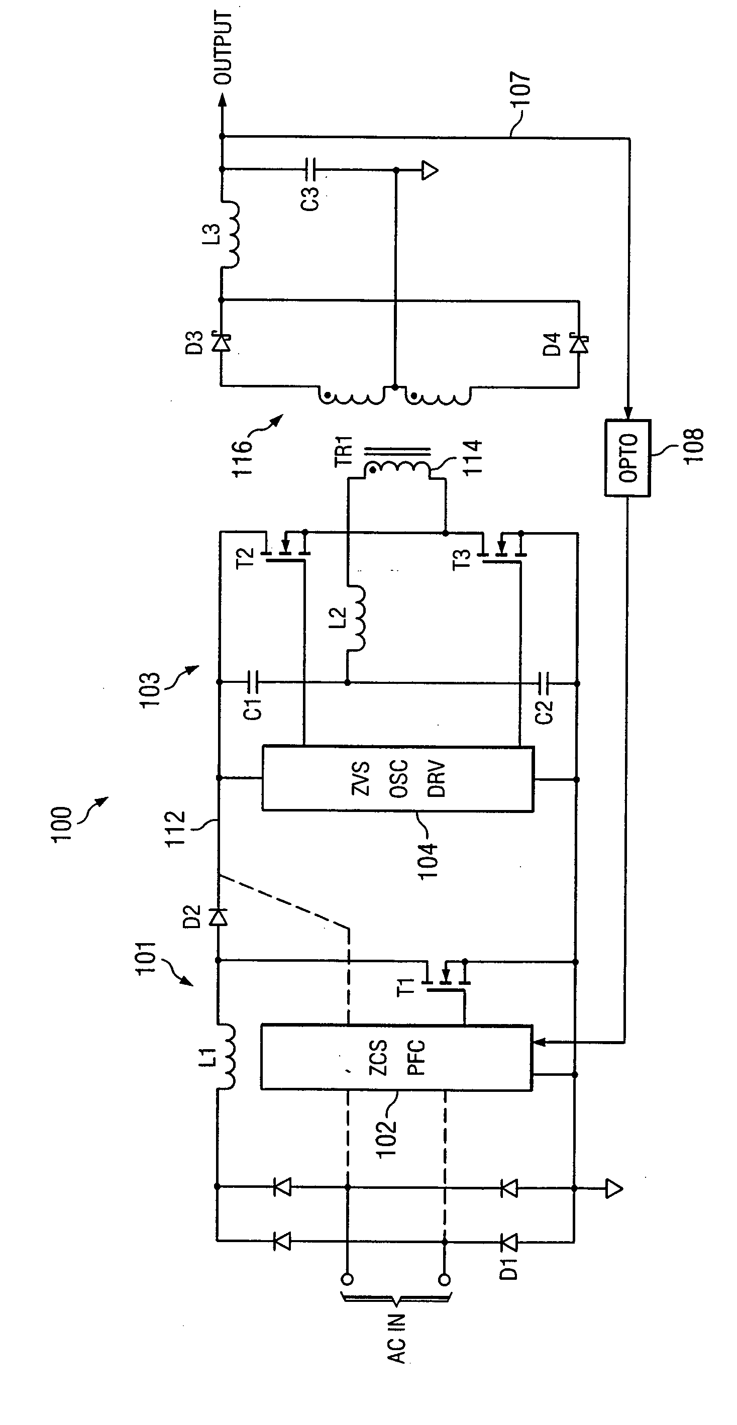
[0006] In accordance with the present invention, an AC-to-DC power converter is provided that is capable of generating a regulated, isolated DC voltage output from a power factor corrected AC voltage input with improved efficiency. In one embodiment, the AC-to-DC power converter is a two-stage power converter including a first power factor correction (PFC) stage connected in series to a second power conversion stage. The PFC stage is operative to perform power factor correction using a zero current switching technique, and the power conversion stage includes a zero voltage switched half-bridge converter. The zero current switching of the PFC stage and the zero voltage switching of the power conversion stage reduce the power requirements and improve the efficiency of the AC-to-DC power converter. The power conversion stage includes a transformer for providing the isolated DC voltage output.
[0008] By providing a zero current switched power factor correction front end followed by a zero voltage switched isolation converter, AC-to-DC power conversion can be achieved with reduced circuit size and complexity, reduced power requirements, and improved efficiency.

Problems solved by technology

The conventional two-stage AC-to-DC power converter described above has drawbacks, however, in that the multiple control loops associated with the first and second stages significantly increase the complexity of the power converter, thereby increasing both the size and cost of manufacture of the overall circuit.

Method used


Image

  • Highly efficient isolated AC/DC power conversion technique
  • Highly efficient isolated AC/DC power conversion technique

Examples


Embodiment Construction

[0012] An AC-to-DC power converter is disclosed that can generate a regulated, isolated DC voltage output from a power factor corrected AC voltage input with improved efficiency. This highly efficient AC-to-DC power converter is a two-stage power converter that includes a zero current switched power factor correction front end followed by a zero voltage switched isolation converter for reducing the size, complexity, and power requirements of the overall circuit.

[0013]FIG. 1 depicts an illustrative embodiment of an AC-to-DC power converter 100, in accordance with the present invention. In the illustrated embodiment, the AC-to-DC power converter 100 is a two-stage power converter comprising a first power factor correction (PFC) stage 101, a second power conversion stage 103, an LC low pass filter including an inductor L3 and a capacitor C3, and a single feedback control loop 107 including an opto-coupler 108. The AC-to-DC power converter 100 is configured to receive an AC power input...


PUM


Abstract

An AC-to-DC power converter that is capable of generating a regulated, isolated DC voltage output from a power factor corrected AC voltage input with improved efficiency. The AC-to-DC power converter is a two-stage power converter including a PFC stage connected in series to a power conversion stage. The PFC stage performs power factor correction using a zero current switching technique, and the power conversion stage includes a zero voltage switched half-bridge converter. The power conversion stage includes a transformer for providing the isolated DC voltage output. The AC-to-DC power converter includes a single feedback control loop for transferring error information from the DC voltage output to the PFC stage, thereby obtaining regulation of the DC voltage output.

Description

CROSS REFERENCE TO RELATED APPLICATIONS [0001] N / A STATEMENT REGARDING FEDERALLY SPONSORED RESEARCH OR DEVELOPMENT [0002] N / A BACKGROUND OF THE INVENTION [0003] The present invention relates generally to AC-to-DC power conversion techniques, and more specifically to a technique for providing a regulated, isolated DC output voltage from a power factor corrected AC input voltage with increased efficiency. [0004] AC-to-DC power converters are known that employ power factor correction techniques to assure low input harmonic current content. For example, a conventional two-stage AC-to-DC power converter comprises a first voltage regulator stage connected in series to a second voltage regulator stage. The first voltage regulator stage includes a power factor corrected front end operative to receive an AC power input, and to convert an AC voltage to a high level regulated DC voltage. The second voltage regulator stage comprises a DC-to-DC power supply section operative to receive the high ...

Claims


Application Information

Patent Timeline
IPC IPC(8): H02M3/335
CPCH02M1/42H02M2001/007Y02B70/12Y02B70/10Y02P80/10H02M1/007
Inventor ANDREYCAK, WILLIAM M.
Owner TEXAS INSTR INC
Learn More