Fuel cell disassembly method and fuel cell

a technology of fuel cell and disassembly method, which is applied in the direction of cell components, primary cell maintenance/service, secondary cell servicing/maintenance, etc., can solve the problems of insufficient movement of linear members, failure to remove sealing layers, and damage to linear members, etc., to achieve the effect of convenient disassembly and assembly

Inactive Publication Date: 2007-04-12
TOYOTA JIDOSHA KK
View PDF4 Cites 12 Cited by
  • Summary
  • Abstract
  • Description
  • Claims
  • Application Information

AI Technical Summary

Benefits of technology

[0029] In the fuel cell of this structure, when the fluid supply for disassembly of the fuel cell is provided to supply the fluid to at least one of the fuel gas conduit and the oxidizing gas conduit, the separator is broken from the breaking guide as the starting point. The fuel cell of this structure is thus readily disassembled.
[0030] In the fuel cell of this structure, a breaking guide may be formed in each of the separators to function as a starting point of breakage of the separator triggered by a fluid supply for disassembly of the fuel cell, which is different from a fluid supply for power generation of the fuel cell, to supply a fluid to at least one of the fuel gas conduit and the oxidizing gas conduit. When the fluid supply for disassembly of the fuel cell, which is different from the fluid supply for power generation of the fuel cell, is carried out to supply the fluid to at least one of the fuel gas conduit and the oxidizing gas conduit, the separator is broken from the breaking guide as the starting point. The fuel cell of this structure is thus readily disassembled.

Problems solved by technology

In the structure of this prior art fuel cell, however, when the linear member is tightly stuck to the sealing layers, the pulling action of the linear member outward may not move the linear member sufficiently or may destroy the linear member.
The sealing layers may thus not be peeled off successfully.
This structure accordingly does not ensure effective and efficient disassembly of the fuel cell.

Method used


Image

  • Fuel cell disassembly method and fuel cell
  • Fuel cell disassembly method and fuel cell
  • Fuel cell disassembly method and fuel cell

Examples


first embodiment

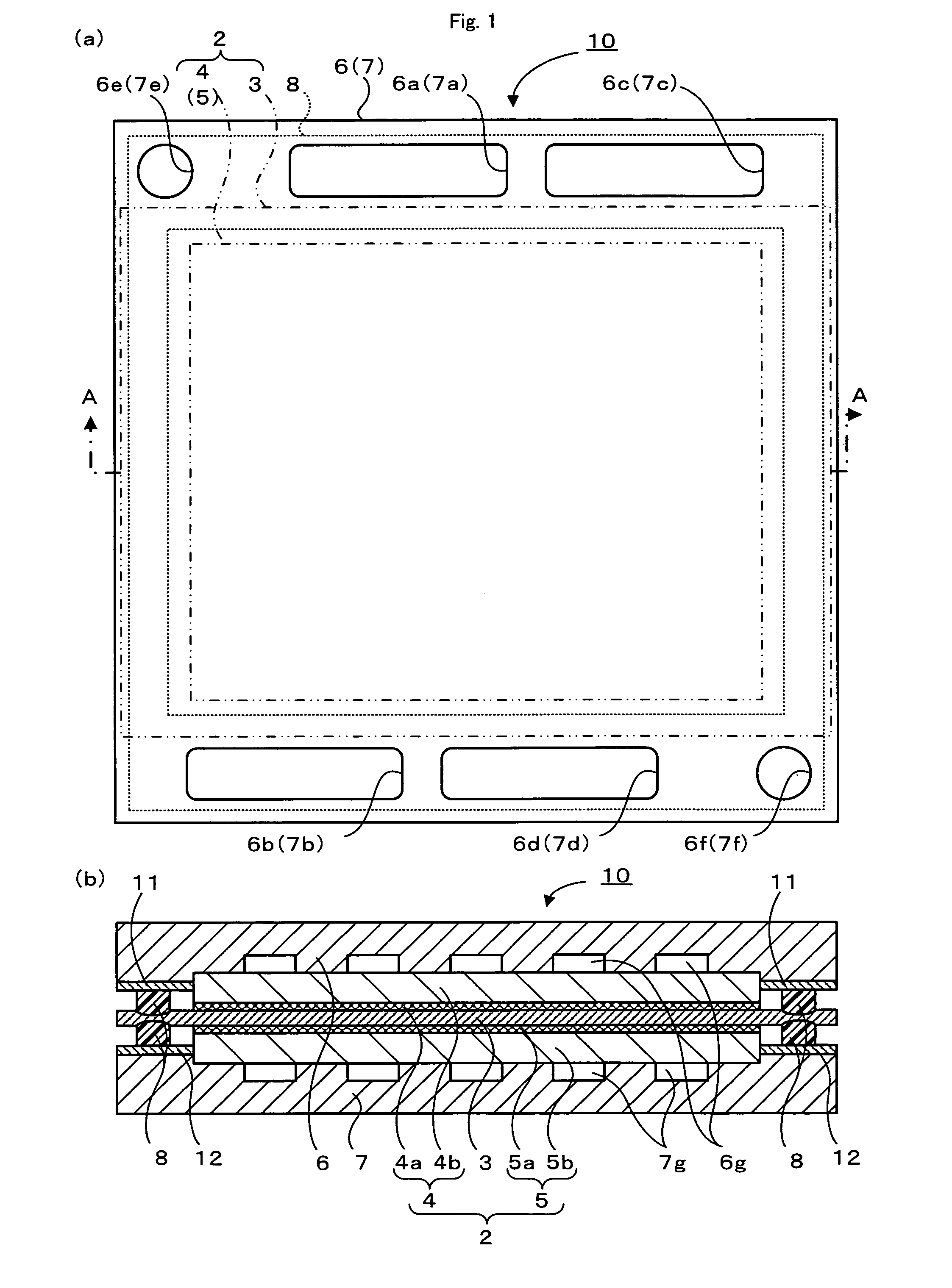
[0049]FIG. 1 schematically illustrates the structure of a fuel cell 10 in a first embodiment of the invention. FIG. 1(a) is a plan view, and FIG. 1(b) is a sectional view taken on a line A-A of FIG. 1(a).

[0050] The fuel cell 10 of this embodiment is a polymer electrolyte fuel cell and includes, as main constituents, a membrane electrode assembly (hereafter referred to as MEA) 2 having an electrolyte membrane 3 interposed between a pair of electrodes 4 and 5, sealing layers 8 located to surround the outer circumference of the MEA 2, and a pair of separators 6 and 7 arranged across the MEA 2 and bonded to the sealing layers 8. The fuel cell 10 is a unit cell having an electromotive force in a range of about 0.6 to 0.8 V. A large number of the fuel cells 10 are tightly laid one upon another to form a direct current power source of several hundred volts as a power supply of, for example, a drive motor of the vehicle.

[0051] The MEA 2 has the electrolyte membrane 3 located between the f...

second embodiment

[0068] A second embodiment of the invention regards a fuel cell stack 50, which is a layered body of plurality of the fuel cells 10. FIG. 11 is a perspective view showing the fuel cell stack 50 in the state of power generation in the second embodiment of the invention. FIG. 12 is a sectional view taken on a line B-B of FIG. 11. In the illustration of FIGS. 11 and 12, the respective constituents of the fuel cells 10 are expressed by the like numerals and symbols to those of the first embodiment.

[0069] As shown in FIG. 11, the fuel cell stack 50 has a cell laminate of the multiple fuel cells 10 of the first embodiment, which are closely and tightly layered one upon another, and end plates 53 and 54 that are arranged across the cell laminate via insulator plates 51 and 52 and are pressed in a compression direction with a pressing force F1 applied by a pressure device (not shown). The fuel cell stack 50 is used as a power source of several hundred volts. The end plate 53 shown on the f...


PUM

PropertyMeasurementUnit
electromotive forceaaaaaaaaaa
temperatureaaaaaaaaaa

Abstract

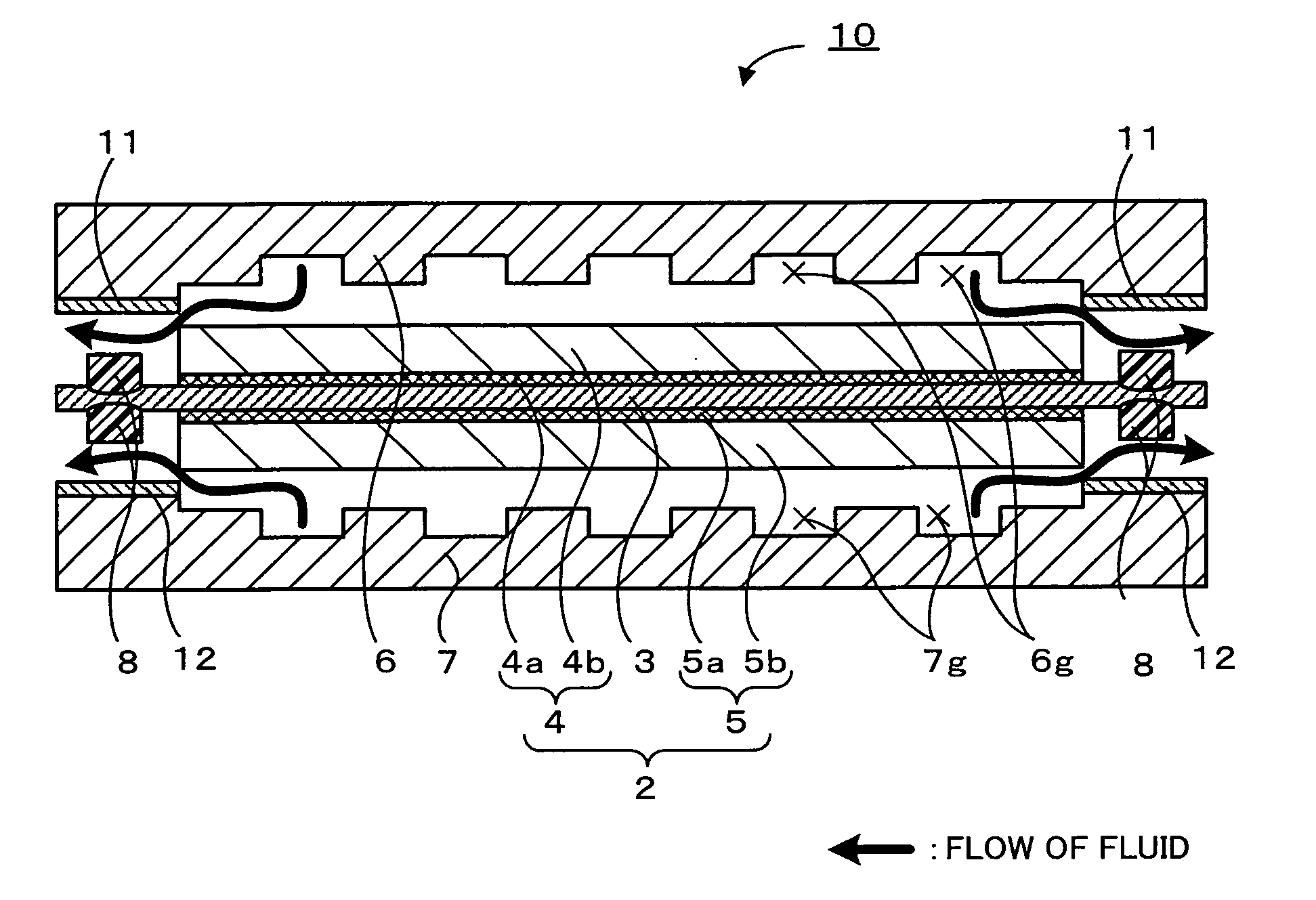
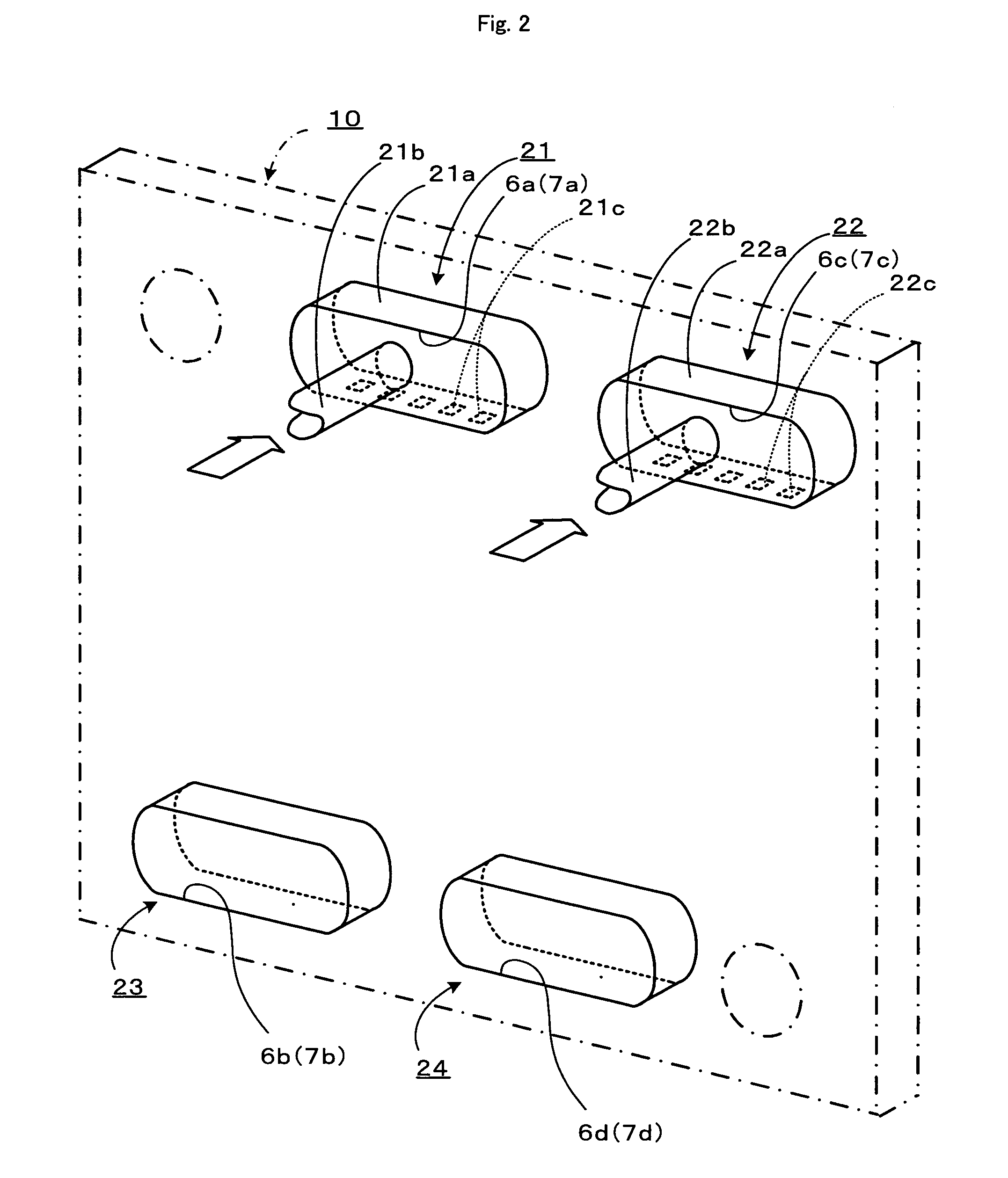
A process of disassembling a fuel cell 10 supplies a fluid to both a fuel gas conduit 6g and an oxidizing gas conduit 7g. Since outlets of the respective gas conduits 6g and 7g are shielded, the internal pressure or in-passage pressure of the respective gas conduits 6g and 7g gradually rises and eventually exceeds a specific in-passage pressure level for power generation of the fuel cell 10. The high in-passage pressure expands a gas diffusion electrode 4b of a membrane electrode assembly (MEA) 2 and a separator 6, which define the fuel gas conduit 6g, in opposite directions to make a clearance between the gas diffusion electrode 4b and the separator 6. Similarly the high in-passage pressure expands a gas diffusion electrode 5b of the MEA 2 and a separator 7, which define the oxidizing gas conduit 7g, in opposite directions to make a clearance between the gas diffusion electrode 5b and the separator 7. The supplied fluid then flows out through these clearances into seals between the separators 6 and 7 and the MEA 2. These flows raise the in-passage pressure and release the seals.

Description

TECHNICAL FIELD [0001] The present invention relates to a fuel cell disassembly method and a fuel cell. BACKGROUND ART [0002] A fuel cell of a known structure includes: an electrode assembly that has an electrolyte interposed between a pair of electrodes; sealing layers that are formed along periphery of the electrode assembly; and a pair of separators that are arranged across the electrode assembly and bonded to the sealing layers, where one of the separators facing one of the electrodes has an oxidizing gas conduit, while the other of the separators facing the other of the electrodes has a fuel gas conduit. In the fuel cell of this known structure, a supply of hydrogen is fed as a fuel gas to the fuel gas conduit, whereas a supply of the air is fed as an oxidizing gas to the oxidizing gas conduit. Hydrogen is separated into proton and electron at one of the electrodes (anode) facing the fuel gas conduit. The proton passes through the electrolyte and shifts to the other electrode (...

Claims


Application Information

Patent Timeline
Patent Type & Authority Applications(United States)
IPC IPC(8): H01M8/02H01M2/08B23P19/00H01M8/04H01M8/24
CPCH01M8/008H01M8/0271Y10T29/49815Y02E60/50H01M8/2465H01M8/2483Y02W30/84H01M8/241H01M8/2457
Inventor SUZUKI, HIROSHITEJIMA, GONAKASHIMA, TOMOAKIAKAGAWA, RYO
Owner TOYOTA JIDOSHA KK
Why Eureka
Try Eureka