Roller chain

a technology of roller chain and roller, which is applied in the direction of driving chain, belt/chain/gearing, chain element, etc., can solve the problems of large friction loss and fuel cost degradation, and achieve the effects of reducing friction loss generated during transmission of power, reducing contact area, and reducing frictional resistan

Inactive Publication Date: 2007-04-12
NAGAO KENICHI
View PDF3 Cites 22 Cited by
  • Summary
  • Abstract
  • Description
  • Claims
  • Application Information

AI Technical Summary

Benefits of technology

[0012] According to the present invention, when the distance from a chain pitch line to an outermost edge surface of the link plate is defined as a backside height, the backside height of the outer link plate is lower than the backside height of the inner link plate. When the chain comes into contact with guide members of a tensioner lever, a guide lever and the like, outermost edge surfaces of the inner link plates only come into contact with the guide members without the contact of the outer link plates therewith. Thus, the contact area can be reduced and frictional resistance can be decreased so that a friction loss generated during transmission of power can be reduced.
[0013] Furthermore, when the outer link is formed of a gourd-shaped outer link plate and the inner link is formed of an cucumber-shaped inner link plate, the distinction between a chain of the present invention and a conventional chain can be easily made and at the same time an incorporation error of the link plate during the manufacture can be prevented. Additionally weight reduction of the chain can be achieved.
[0014] Also, when selected said outer links are formed of non-concave ellipsoidal outer link plates and the remaining outer links are formed of concave outer link plates and the inner links are formed of a non-concave ellipsoidal inner link plate, the distinction between a chain of the present invention and a conventional chain is even more easily made.

Problems solved by technology

Particularly, when the roller chain 31 is incorporated into an automobile engine and is used as a timing chain, there is a problem that a large friction loss deteriorates fuel cost.

Method used


Image

  • Roller chain
  • Roller chain
  • Roller chain

Examples


example 1

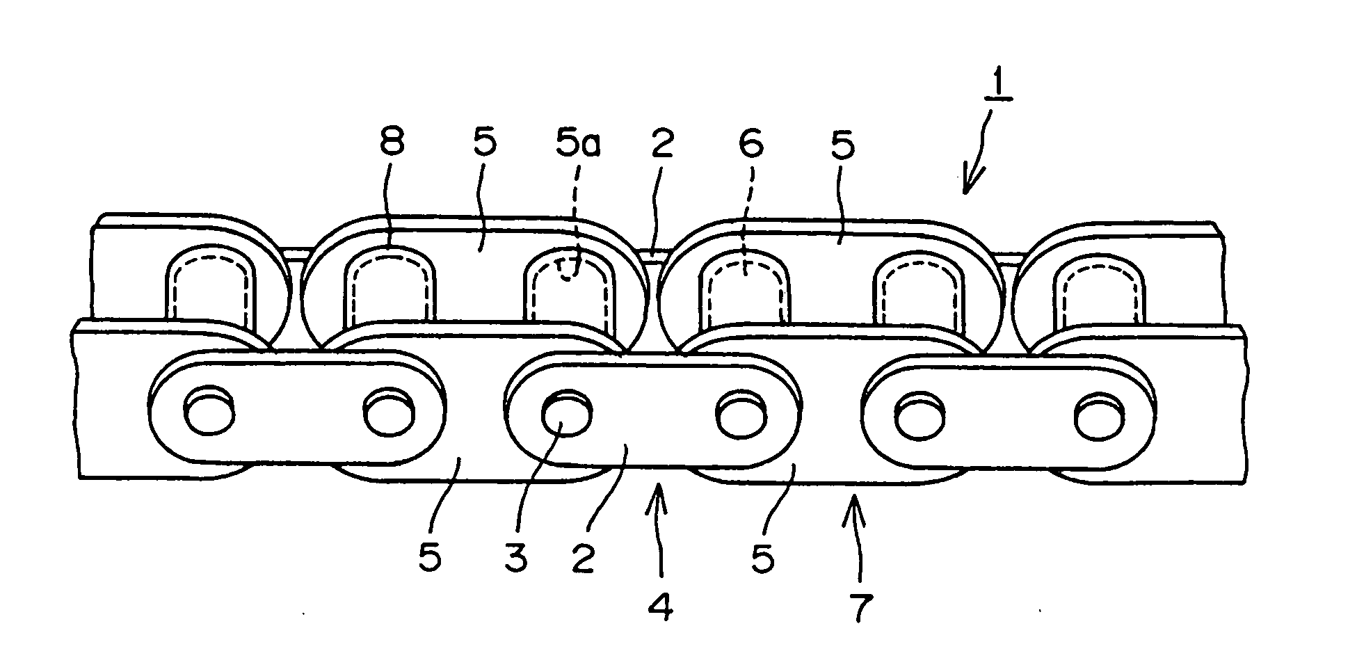
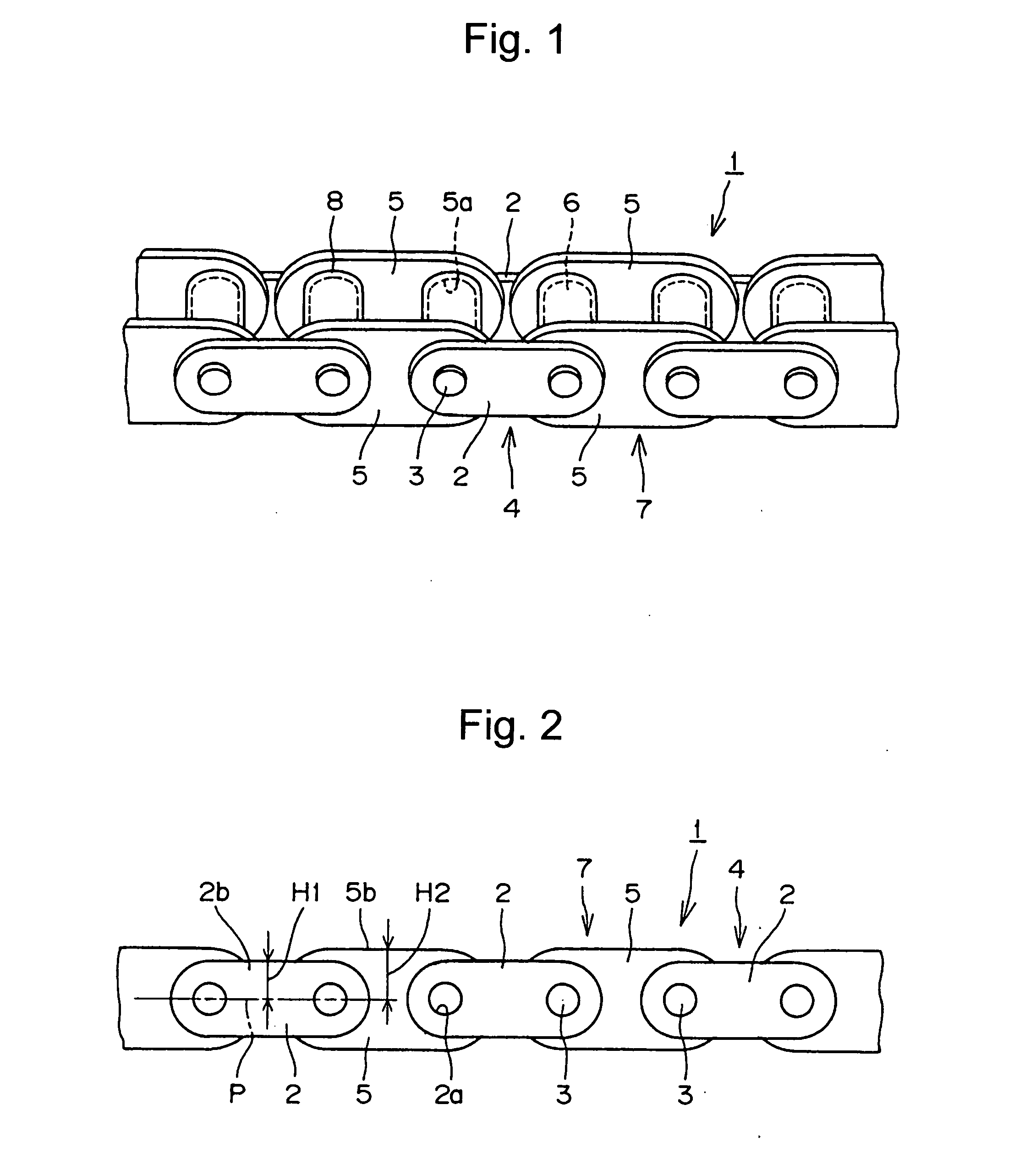
[0024] Example 1 of the present invention will be described with reference to FIGS. 1 and 2. FIGS. 1 and 2 are a partial perspective view and a partial side view of a roller chain 1 respectively while showing exaggeratedly that the backside height of an outer link plate is lower than the backside height of an inner link plate.

[0025] A roller chain 1 comprises outer link plate assemblies 4 in each of which pins 3 span between and are force-fit into pin holes 2a of a pair of outer link plates 2, and inner link assemblies 7 in each of which bushes 6 span between and are force-fit into bush holes 5a of a pair of inner link plates 5, and a roller 8 is rotatably loosely fitted onto this bush 6. Al of the link plates are ellipsoidal, having semi-circular end portions connected by a mid-portion. The pin holes 2a and bush holes 5a are positioned in the centers of the semi-circular ends portions. The roller chain 1 is flexibly formed such that the outer link assembly 4 and the inner link asse...

example 2

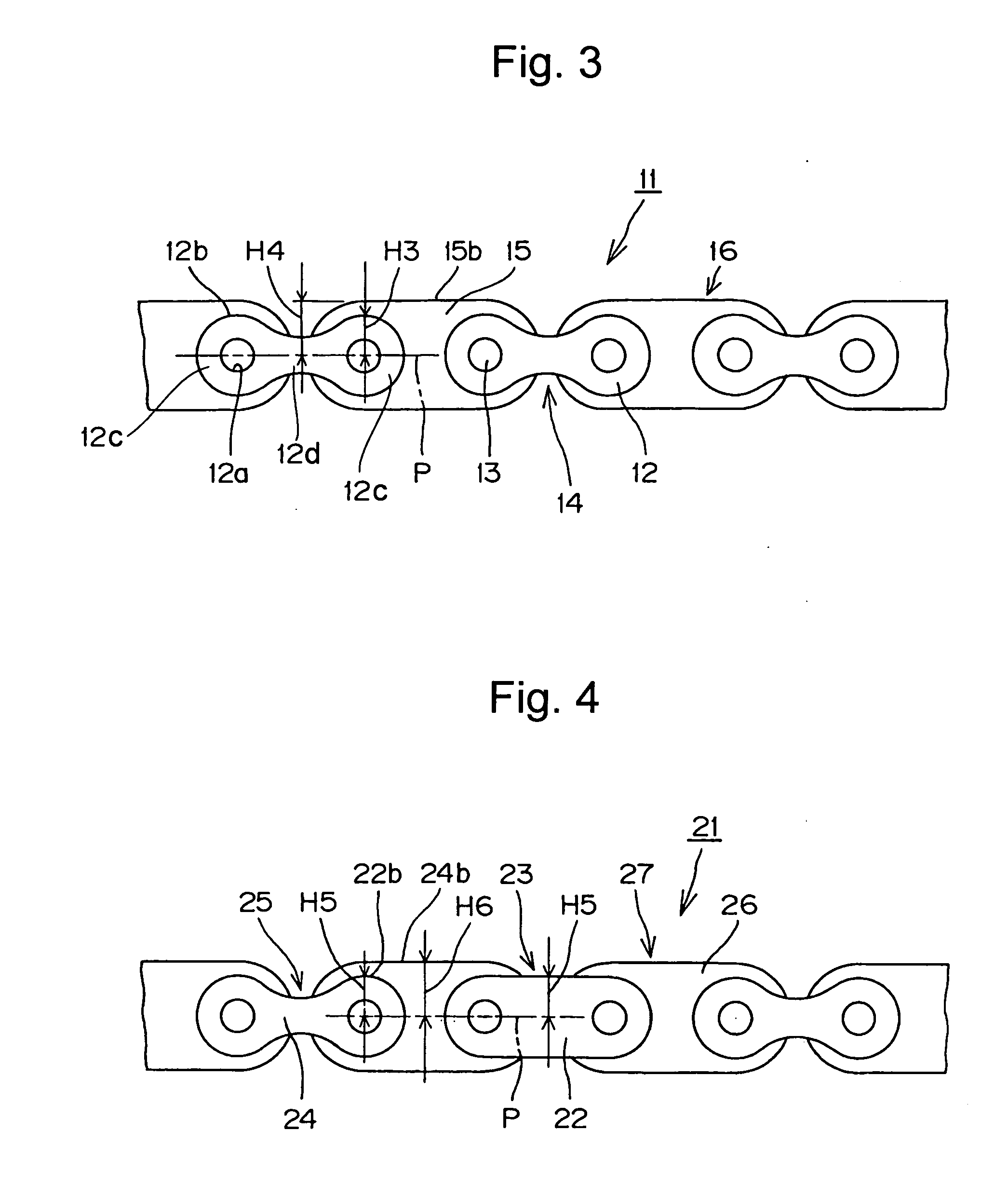
[0029] Example 2 of the present invention will be described with reference to FIG. 3. FIG. 3 is a partial side view of a roller chain 11 while showing exaggeratedly that the backside height of an outer link plate is lower than the backside height of an inner link plate. The roller chain 11 of Example 2 corresponds to one using an outer link assembly 14 consisting of gourd-shaped outer link plates 12. The gourd-shaped outer link plates 12 are formed with semi-circular end portions 12c connected by a concave mid-portion 12d.

[0030] A roller chain 11 comprises outer link assemblies 14 in each of which pins 13 are force-fit into pin holes 12a of a pair of outer link plates 12, and inner link assemblies 16 in each of which bushes (not shown) are force-fit into bush holes (not shown) of a pair of inner link plates 15, and a roller is rotatably loosely fitted onto this bush. And the roller chain 11 is flexibly formed such that the outer link assembly 14 and the inner link assembly 16 are a...

example 3

[0035] Example 3 of the present invention will be described with reference to FIG. 4. FIG. 4 is a partial side view of a roller chain 21 while showing exaggeratedly that the backside height of an outer link plate is lower than the backside height of an inner link plate. The roller chain 21 of Example 3 is flexibly formed such that it comprises outer link assemblies 23 each comprising a pair of ellipsoidal outer link plates 22, outer links 25 each comprising a pair of gourd-shaped outer link plates 24, and inner link assemblies 27 each comprising a pair of ellipsoidal inner link plates 26 and the outer link assembly 23, outer link 25 and the inner link assembly 27 are alternately connected to each other. It is noted that the outer link assembly 23 and the outer link 25 may be alternately arranged one by one, or in another sequence.

[0036] Further, when a distance from a pitch line P of the roller chain 21 to outermost edge surfaces 22b, 24b of the outer link plates 23, 24 is defined a...


PUM


Abstract

A roller chain, in which when the roller chain comes into contact with guide members, the contact area is reduced, so that frictional resistance is decreased and friction loss generated during transmission of power is reduced. A roller chain is formed such that an outer link assembly comprising a pair of outer link plates and an inner link assembly comprising a pair of inner link plates are alternately connected along the pitch line of the chain to each other by pins. The distance from the pitch line of the roller chain to outermost edge surfaces of the link plates is the backside height. The backside height of the outer link plates is lower than the backside height of the inner link plates. When the roller chain contacts and slides on the guide members, the outer link plate does not come into contact with the guide members so that friction loss can be reduced. In some embodiments, some of the link plates are concave ellipsoidal (gourd-shaped) and others are non-concave ellipsoidal (cucumber-shaped).

Description

FIELD OF INVENTION [0001] The present invention relates to a roller chain used in a timing drive system in an internal-combustion engine such as an automobile engine or the like, and more specifically relates to a roller chain, which can reduce a friction loss due to sliding friction with a guide member such as a tensioner lever, a guide lever or the like. BACKGROUND OF THE INVENTION [0002] Recently, as a timing drive chain in an automobile engine, a roller chain has been adopted in place of a toothed belt, which has been often used from the needs of high load, high speed, maintenance-free and the like, such as shown in FIG. 5. (Also see Japanese Laid-Open Patent Publication No. 2004-257531). [0003] When a roller chain is used in a timing drive system in an automobile engine; a timing chain Tc is wrapped around a crank sprocket S1 and cam sprockets S2, S2. This timing chain Tc contact-slides on guide members of a tensioner lever G1, a guide lever and the like, which are adapted to a...

Claims


Application Information

Patent Timeline
Patent Type & Authority Applications(United States)
IPC IPC(8): F16G13/02
CPCF16G13/06
Inventor NAGAO, KENICHI
Owner NAGAO KENICHI
Why Eureka
Try Eureka