Sensing apparatus and method

Active Publication Date: 2007-04-19
GARRETT THERMAL SYST LTD
View PDF18 Cites 47 Cited by
  • Summary
  • Abstract
  • Description
  • Claims
  • Application Information

AI Technical Summary

Benefits of technology

[0019] In essence the present invention stems from the realisation that a determination of the arrival time of a signal is readily ascertained when a signal with a portion specifically modified is overlaid in time relative to an unmodified signal. This solution obviates the need for sophisticated electronics used to find a predetermined marker buried within a given received signal transmission, which manifests itself as an unpredictable received signal waveform distortion that is als

Problems solved by technology

However, this empirically determined flow rate is not accurate and is corrected for variation in the propagation rate of the transmitted ultrasound pulses by deriving a correlation factor from the output signal of the second transducer.
Freund et al does not disclose any processing operations for the signal a

Method used


Image

  • Sensing apparatus and method
  • Sensing apparatus and method
  • Sensing apparatus and method

Examples


Embodiment Construction

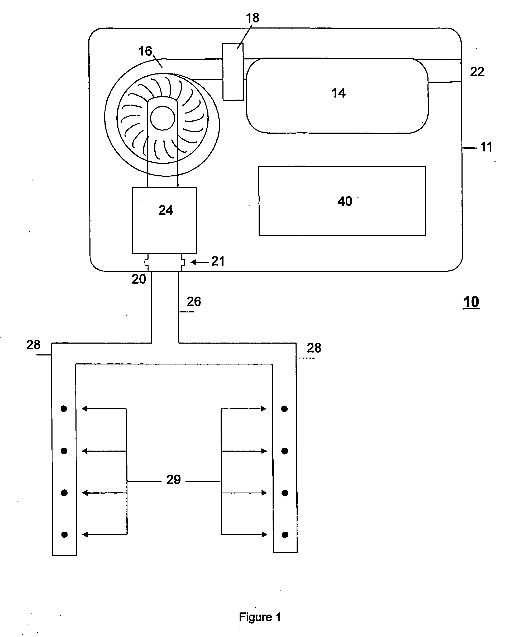
[0141] A particle detector system in the form of a smoke detector 10, shown in FIG. 1, comprises a housing 11 attached to a conduit or flow channel 26. The detector 10 has a number of component parts comprising a detector chamber 14, an aspirator 16, a filter 18, a fluid inlet 20 and a fluid outlet 22. For purposes of clarity the precise fluid flow path within the chamber 14 is not shown in FIG. 1.

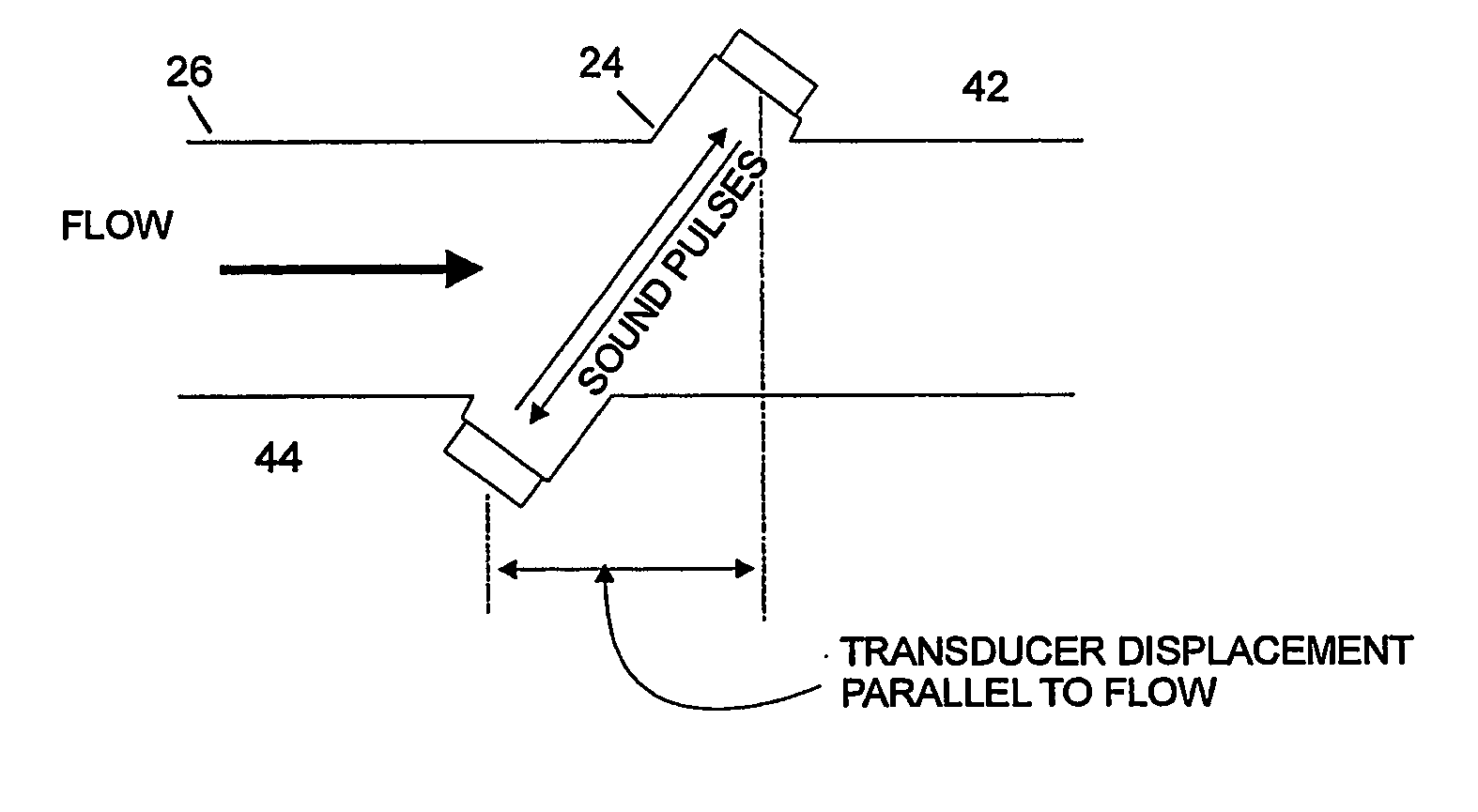
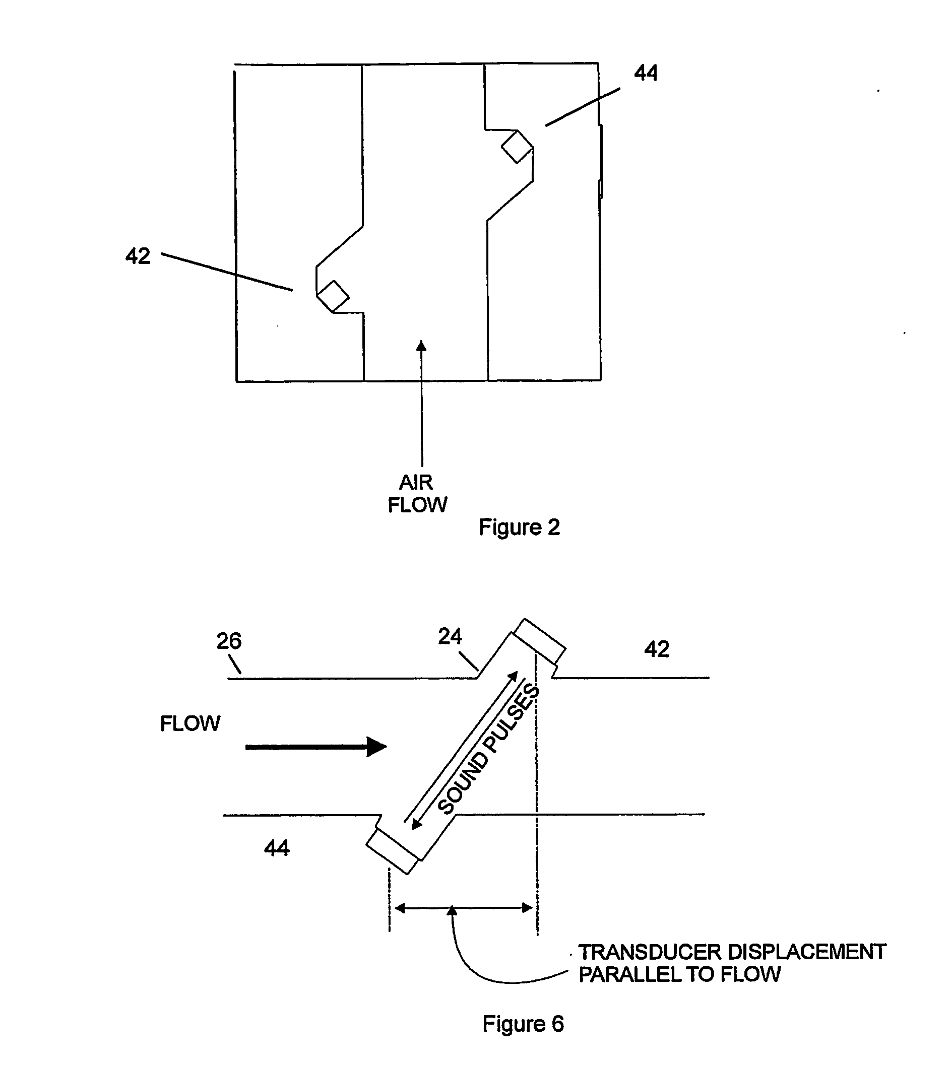
[0142] Also associated with the smoke detector 10 is a flow sensor 24. In FIG. 1 the flow sensor 24 is in fluid communication with the inlet 20 and aspirator 16.

[0143] Conduit 26 is connected to a network of pipes 28. Each pipe 28 has a number of sampling points 29, which may comprise holes. The sampling points 29 allow air to be sampled at various places in an area to be protected, such as a building (not shown). The aspirator 16 draws air into the sampling points 29 through the pipe network 28, through the inlet 20 and into the housing 11. The air sample then passes into the flow senso...


PUM


Abstract

The present invention relates to the field of sensing apparatus (10) in detecting particles in air sampled from a number of locations. In one aspect the present invention provides for the determination of the time of flight of a signal transmitted between a transmitter (42, 44) and a receiver (44, 42), comprising: transmitting a first signal comprising at least one characteristic waveform feature; transmitting a second signal comprising at least one characteristic waveform feature and a waveform modification introduced at a predetermined point in time of the duration of the second signal; receiving said first and second transmitted signals; determining a point of diversion between corresponding characteristic waveform features of the first and second received signals comprising super positioning said first and second received signals such that said point of diversion corresponds to an arrival time of the introduced waveform feature modification at the receiver. In a preferred embodiment, the invention provides an accurate time of flight determination of ultrasonic signals in a flow sensor (24) adapted for a smoke detector system (10).

Description

RELATED APPLICATIONS [0001] This application claims priority to Australian Provisional Patent Application No. 2003902318, filed 14 May 2003 and entitled “Improved Sensing Apparatus and Method” and, the specification thereof is incorporated herein by reference in its entirety and for all purposes. [0002] 1. Field of Invention [0003] The present invention relates to the field of sensing apparatus. In particular, the present invention relates to an improved particle detector and method for detecting particles in air. In one form, the invention relates to an improvement in particle detectors and an associated method of detecting particles in air sampled from a number of locations. It will be convenient to hereinafter describe the invention in relation to the use of an ultrasonic means of flow sensing within an aspirated smoke detector system, however, it should be appreciated that the present invention may not be limited to that use, only. [0004] 2. Related Art [0005] The inventor has i...

Claims


Application Information

Patent Timeline
IPC IPC(8): G01H5/00G01F1/66G01N1/22G01N1/26G01N15/00G01N15/14G01N29/024G08B17/10
CPCG01F1/667G01N1/2205G01N1/2273G01N1/26G01N29/024G08B17/10G01N2015/1486G01N2291/0217G01N2291/02408G01N2291/02836G01N2015/0046G08B17/113G01F1/66G01F1/74
Inventor AJAY, KEMALCAPRIHAN, ARJUN VINOOREZNY, MICHAEL
Owner GARRETT THERMAL SYST LTD
Why Eureka
Try Eureka