Method and apparatus for inspecting pneumatic tire during production

Inactive Publication Date: 2007-04-19
TOYO TIRE & RUBBER CO LTD
View PDF9 Cites 34 Cited by
  • Summary
  • Abstract
  • Description
  • Claims
  • Application Information

AI Technical Summary

Benefits of technology

[0022] Additionally, since defects can be detected in the midst of production in such a way, the defects so detected can be dealt within the early step, thereby making it possible to reduce the generation of the defects substantially, thus reducing costs for materials.

Problems solved by technology

Low uniformity of pneumatic tires causes vibrations in a vehicle.
The variability of constituent members of tires being produced that occurs in steps of the tire production process is considered to constitute one of the causes which deteriorate the uniformity of completed tires.
Conventionally, however, there has existed no process control system which controls the production process from the viewpoint of the uniformity, and hence, it is not until the uniformity of a completed tire is measured that a defect associated with low uniformity is found.
This cause locating process is the case that often happens with the deteriorated uniformity-related defect.
Due to this way of dealing with the defect, there have been caused problems that all tires that had passed through the relevant step until the defect was found are now defective, making lots of defectives to be discarded and that the production, which had been stopped when the defect was found, cannot not be resumed until the cause is verified.
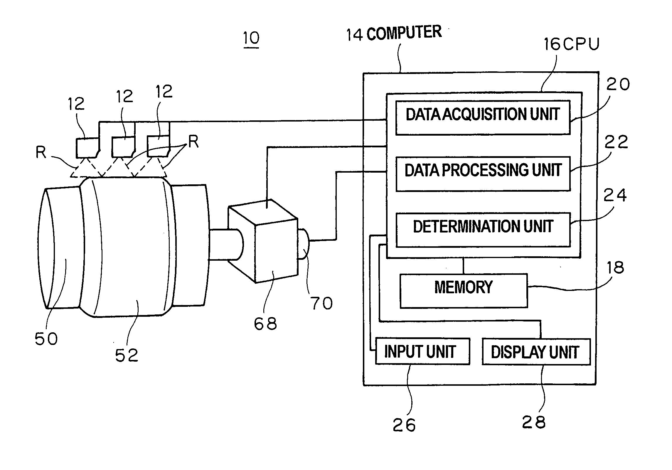
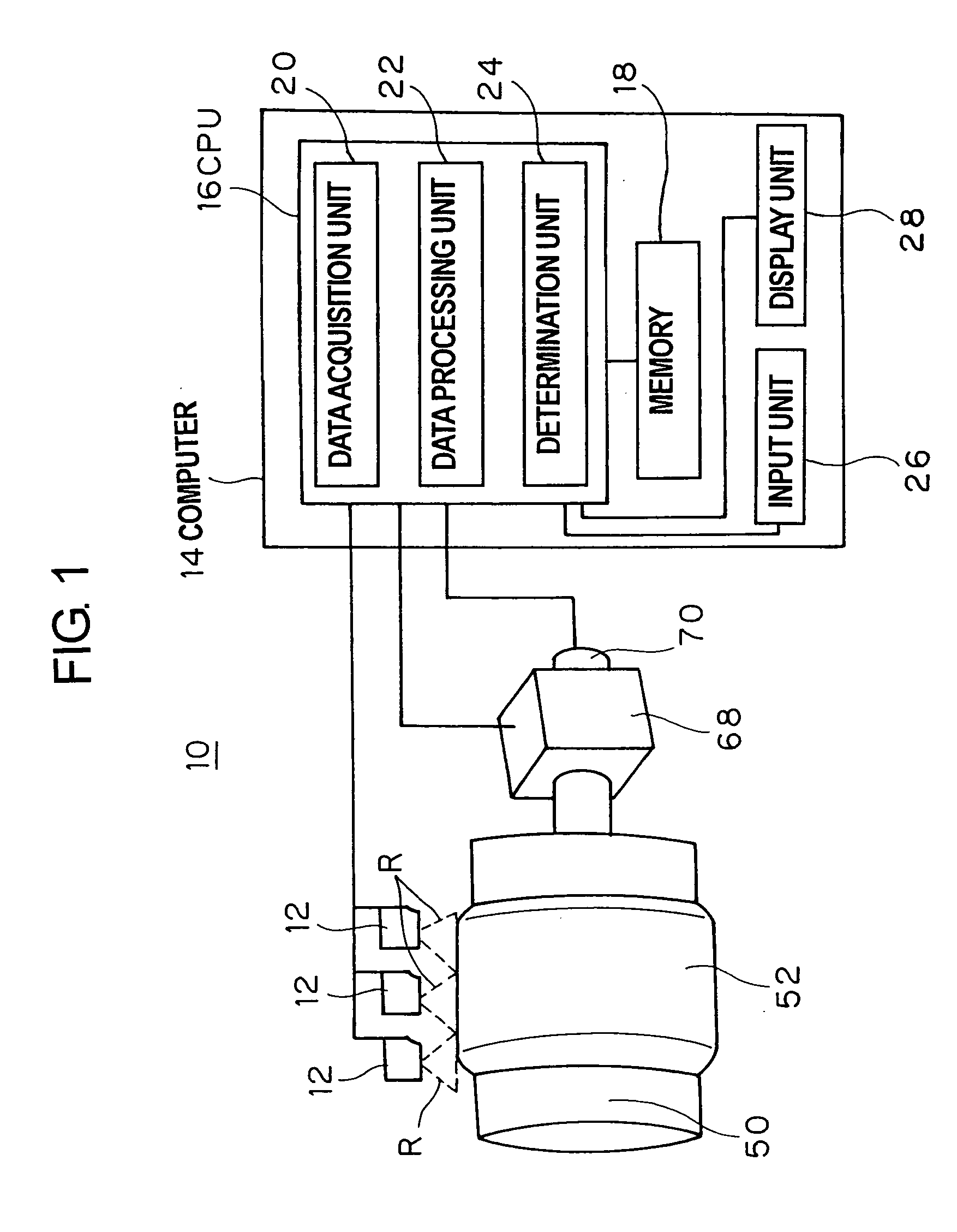
While it is considered to measure a fluctuation on the circumference of a tire using the laser sensor in the way described above, in a tire fabrication technique of affixing a ribbon-shaped material, since there are caused irregularities in a lateral direction, the evaluation of only a single point in the lateral direction by the one-dimension laser sensor is insufficien

Method used


Image

  • Method and apparatus for inspecting pneumatic tire during production
  • Method and apparatus for inspecting pneumatic tire during production
  • Method and apparatus for inspecting pneumatic tire during production

Examples


Embodiment Construction

[0031] Hereinafter, an embodiment of the invention will be described by reference to the accompanying drawings.

[0032]FIG. 1 is an exemplary diagram which shows the configuration of an inspection apparatus 10 according to an embodiment of the invention. This inspection apparatus 10 includes a two-dimension laser sensor 12 which are provided in close proximity to an object 52 built on a tire building drum 50 and a computer 14.

[0033] The annular object 52 which makes up part of a tire is built on the tire building drum 50. In an example shown in FIG. 4, this object 52 is built by winding spirally a ribbon-shaped rubber 54 on the tire building drum 50 along a circumferential direction of the tire in such a manner as to overlap, so as to make up a tread portion 56 of the tire (refer to FIG. 3). To be more specific, a green tire is formed on the tire building drum 50 which is a tire which has not yet been vulcanized but has been built, and a tread portion thereof is formed by winding th...


PUM

PropertyMeasurementUnit
Widthaaaaaaaaaa

Abstract

There is provided an inspection method for inspecting an object built on a tire building drum to make up a pneumatic tire with respect to profile thereof in process of production of the tire includes, in which data with respect to a profile of the object for a single rotation of the tire building drum is acquired by a two-dimension laser sensor having a detection range along a lateral direction of the object while rotating the drum. Then, using the data so acquired, a radial run-out (RRO) in a circumferential direction of the tire is averaged out in a lateral direction of the object for harmonic analysis, and whether or not the magnitude of the harmonic obtained as a result of the analysis falls within a predetermined range is determined.

Description

CROSS-REFERENCE TO RELATED APPLICATION [0001] This application is based upon and claims the benefit of priority from the prior Japanese Patent Application No. 2005-302234, filed on Oct. 17, 2005; the entire contents of which are incorporated herein by reference. BACKGROUND OF THE INVENTION [0002] 1. Field of the Invention [0003] The present invention relates to a method and apparatus for inspecting a pneumatic tire with respect to at least part of a profile thereof during production. The invention also relates to a method for producing a pneumatic tire by making use of the inspection method. [0004] 2. Description of the Related Art [0005] Low uniformity of pneumatic tires causes vibrations in a vehicle. Due to this, force variations occurring when they rotate are measured on pneumatic tires after production, and tires showing large force variations are disposed as defectives. [0006] The variability of constituent members of tires being produced that occurs in steps of the tire produ...

Claims


Application Information

Patent Timeline
IPC IPC(8): B29D30/08
CPCB29D30/0061G01B5/252G01B11/2522G01M17/027
Inventor MORIGUCHI, KINYAWATANABE, HAJIMEYAMASHITA, OSAMU
Owner TOYO TIRE & RUBBER CO LTD
Why Eureka
Try Eureka