Lighting system

a light-emitting system and light-emitting technology, applied in the direction of static indicating devices, instruments, semiconductor lamp usage, etc., can solve the problems of color shift and color shift cannot be solved, and achieve the effect of low emission color change and high luminan

Active Publication Date: 2007-04-19
SEMICON ENERGY LAB CO LTD
View PDF53 Cites 10 Cited by
  • Summary
  • Abstract
  • Description
  • Claims
  • Application Information

AI Technical Summary

Benefits of technology

[0010] In view of the above problem, it is an object of the present invention to provide a lighting system which uses a stacked light emitting element provided with a plurality of light emitting units and causes little change in emission color even after being used for a long time.

Problems solved by technology

As for such a light emitting element, there are many problems depending on materials in improving element characteristics, and improvement in element structure, development of materials, and the like are conducted to overcome the problems.
However, a light emitting element provided with a plurality of light emitting units has a problem causing color shift where an emission color of the light emitting element changes as time passes unless light emitting units to be combined with each other have the same length of life.
As for a decrease of luminance, constant luminance can be maintained by increasing a voltage to be applied, but color shift cannot be solved only by adjusting a voltage to be applied.

Method used


Image

  • Lighting system
  • Lighting system
  • Lighting system

Examples


embodiment mode 1

(Embodiment Mode 1)

[0038] This embodiment mode explains one mode of a lighting system of the present invention.

[0039] As for the lighting system of the present invention, a light emitting region is divided into a plurality of regions, and each of the divided light emitting regions includes a plurality of light emitting elements. One is a stacked light emitting element in which a plurality of light emitting units is stacked, and another is a correction light emitting element. The stacked light emitting element is referred to as a first light emitting element, and the correction light emitting element is referred to as a second light emitting element.

[0040] The first light emitting element is formed by stacking a plurality of light emitting units so as to provide a desired emission color as a whole. In other words, the first light emitting element is formed so that an initial emission color is a desired first emission color. For example, in the case of a light emitting element in wh...

embodiment mode 2

(Embodiment Mode 2)

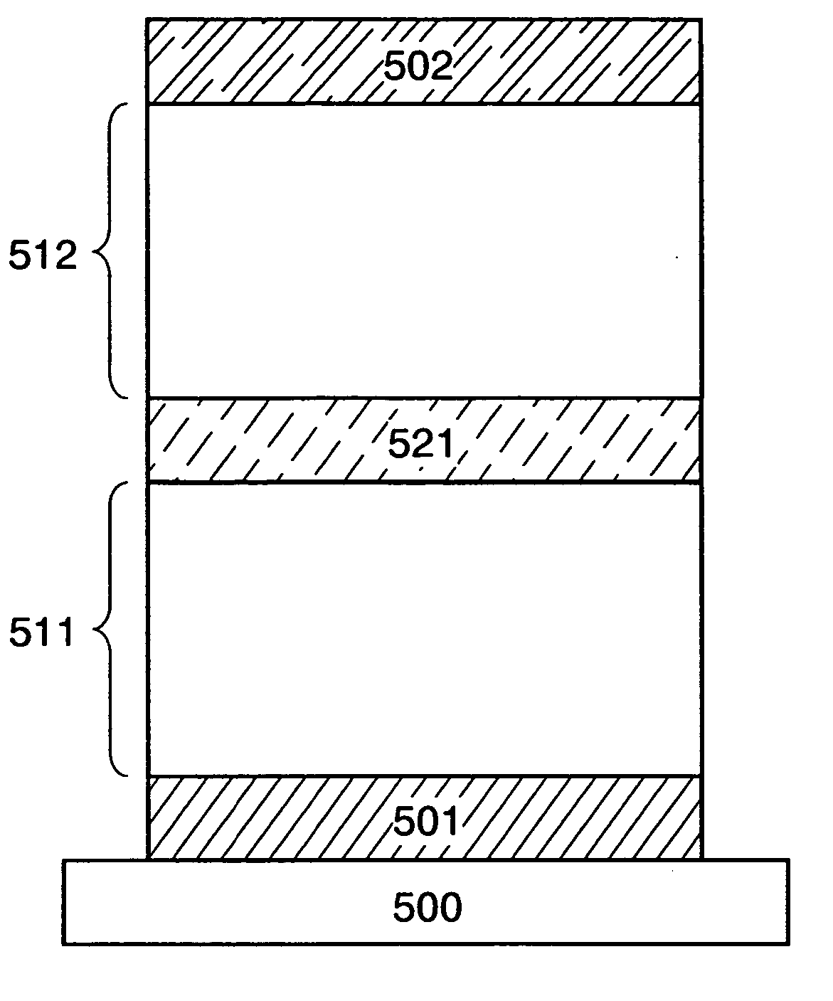
[0045] This embodiment mode explains a stacked light emitting element used for a lighting system of the present invention with reference to FIG. 5. The stacked light emitting element has a structure in which a plurality of light emitting units is stacked with a charge generation layer interposed therebetween. FIG. 5 shows a structure in which two light emitting units are stacked as one mode of the stacked light emitting element. In addition, this embodiment mode explains the case where a first electrode 501 functions as an anode and a second electrode 502 functions as a cathode.

[0046] A substrate 500 is used as a support for the light emitting element. For the substrate 500, for example, glass, plastic, or the like can be used. Note that another material may alternatively be used as long as it functions as a support in a manufacturing process.

[0047] For the anode, various materials can be used, and metal, an alloy, a conductive compound, a mixture thereof, or th...

embodiment mode 3

(Embodiment Mode 3)

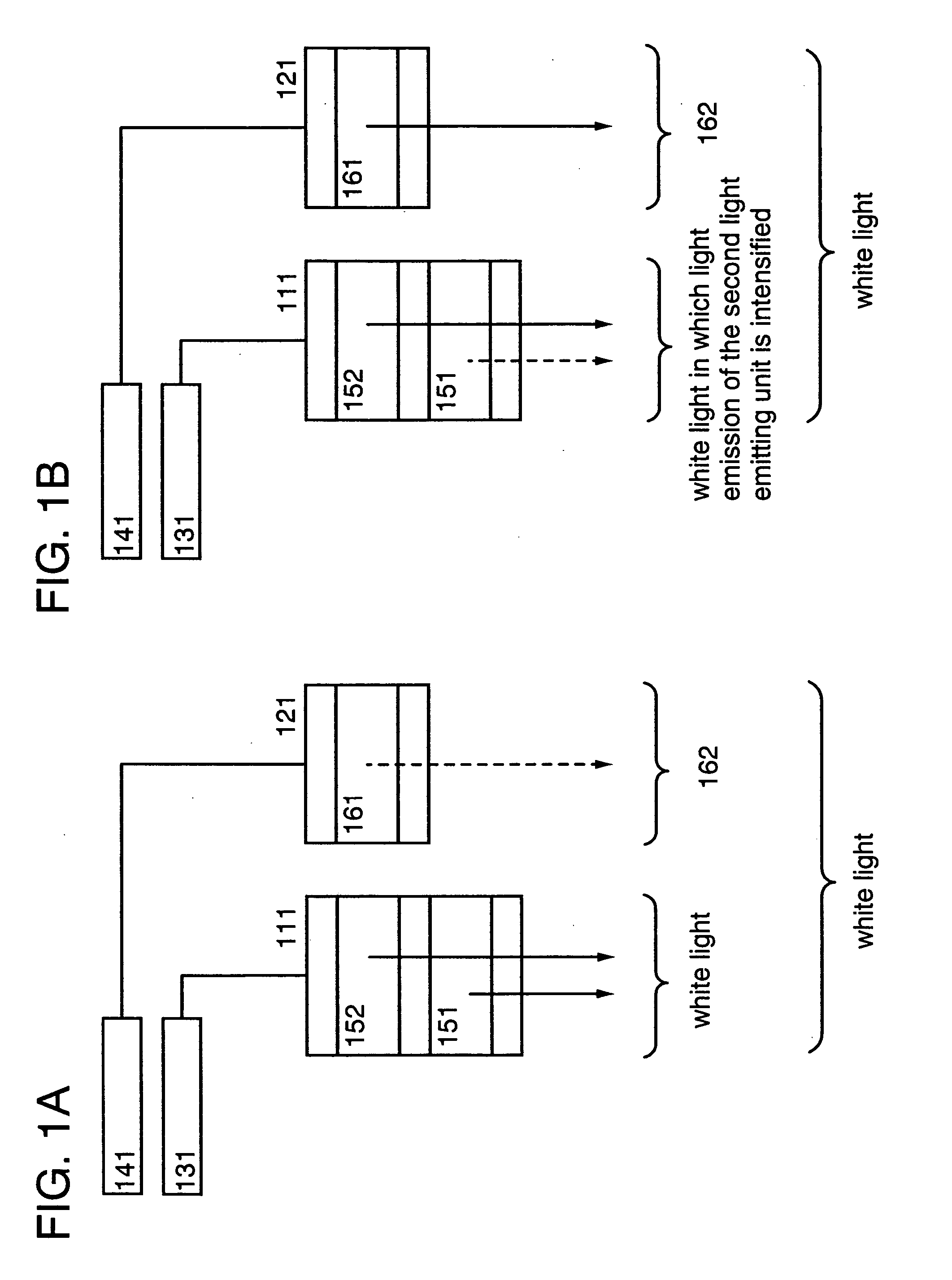
[0061] This embodiment mode explains a lighting system which uses a stacked light emitting element including two light emitting units as a first light emitting element and a light emitting element including one light emitting unit as a second light emitting element, with reference to FIGS. 1A and 1B. Although this embodiment mode explains the case where a divided light emitting region emits white light, the present invention can be applied to a case other than the case of white light emission.

[0062] In this embodiment mode, a first light emitting element 111 is a stacked light emitting element including two light emitting units. A first light emitting unit 151 and a second light emitting unit 152 contain different light emitting materials and emit light of different colors. For example, white light emission can be achieved by forming the first light emitting unit 151 to emit blue light and the second light emitting unit 152 to emit orange light and optimizing thi...


PUM


Abstract

An object of the present invention is to provide a lighting system which uses a stacked light emitting element provided with a plurality of light emitting units and causes little change in emission color even after being used for a long time. A lighting system is provided, which includes a first light emitting element including a plurality of light emitting units; a second light emitting element; a first control means which controls light emission of the first light emitting element; and a second control means which controls light emission of the second light emitting element, where the first light emitting element emits light of a first emission color that is an initial emission color and a second emission color that is an emission color after change over time, and the second light emitting element emits light of a complementary color of the second emission color. With the above structure, color shift due to change over time can be suppressed.

Description

BACKGROUND OF THE INVENTION [0001] 1. Field of the Invention [0002] The present invention relates to a light emitting device which uses a light emitting element utilizing electroluminescence, and particularly, a lighting system. [0003] 2. Description of the Related Art [0004] A light emitting element is a self-light emitting element and attempted to be used as a lighting system. The lighting system using the light emitting element can provide lighting systems tailored to customers' needs such as high efficiency and excellent color rendering properties. [0005] It is said that a light emitting mechanism of the light emitting element emits light by applying a voltage between a pair of electrodes where a light emitting layer is interposed, so that electrons injected from a cathode and holes injected from an anode are recombined with each other at a light emitting center of the light emitting layer to form molecular excitons and the molecular excitons release energy when returning to a g...

Claims


Application Information

Patent Timeline
Patent Type & Authority Applications(United States)
IPC IPC(8): H01L29/06H05B44/00
CPCG09G3/3208G09G3/3216G09G3/3225G09G2320/048G09G2320/0666H01L27/3211H01L27/3244H01L51/5036H01L51/5278H05B33/0896H05B45/60Y02B20/30H10K59/35H10K59/12H10K50/125H10K50/19
Inventor SAKATA, JUNICHIRO
Owner SEMICON ENERGY LAB CO LTD
Why Eureka
Try Eureka