Photonic structures for efficient light extraction and conversion in multi-color light emitting devices

a light-emitting device and photonic structure technology, applied in the field of photonic crystals and light-emitting diodes, can solve the problems of other colored light generation, lack of efficiency of green-yellow visible spectrum, and combination of different colors on a single substrate, so as to achieve high light extraction efficiency, efficient excitation of the ses, and high efficiency

Inactive Publication Date: 2007-04-19
RGT UNIV OF CALIFORNIA
View PDF15 Cites 124 Cited by
  • Summary
  • Abstract
  • Description
  • Claims
  • Application Information

AI Technical Summary

Benefits of technology

[0038] The present invention discloses design principles for and examples of high efficiency, bright, light emitting diodes (LEDs) emitting at various wavelengths by use of several emitting species and optimized photonic crystals. The LED is comprised of a substrate, a buffer layer grown on the substrate (if such a layer is needed), a first active region comprising primary emitting species (PES) that are electrically-injected

Problems solved by technology

The green-yellow portion of the visible spectrum is thus still lacking efficiency, while the combination of different colors on a single substrate (for example, as required in RGB pixels for color display applications, for white light emission, or for any other colored light generation requiring color mixing) is very limited with the semiconductors grown by the conventional methods mentioned previously.
Color rendering, mixing, the different directionalities of the LED (directional) and phosphors (isotropic) emissions, and the overall efficiency of such devices are the most important issues related to this scheme.
However, the overall efficiency is still low.
However, one of the major difficulties with such semiconductor-based structures is caused by the loss of large portions of both PES and SES light emis

Method used


Image

  • Photonic structures for efficient light extraction and conversion in multi-color light emitting devices
  • Photonic structures for efficient light extraction and conversion in multi-color light emitting devices
  • Photonic structures for efficient light extraction and conversion in multi-color light emitting devices

Examples


Embodiment Construction

[0052] In the following description of the preferred embodiment, reference is made to the accompanying drawings which form a part hereof, and in which is shown by way of illustration a specific embodiment in which the invention may be practiced. It is to be understood that other embodiments may be utilized and structural changes may be made without departing from the scope of the present invention.

Overview

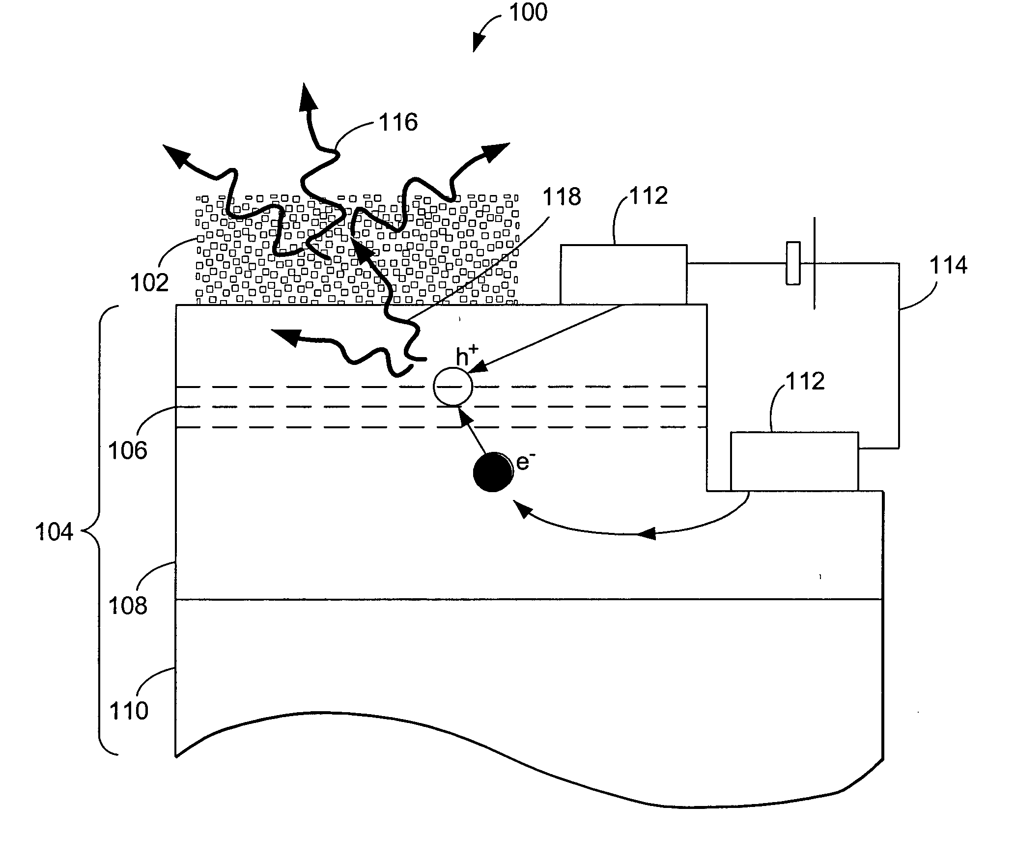
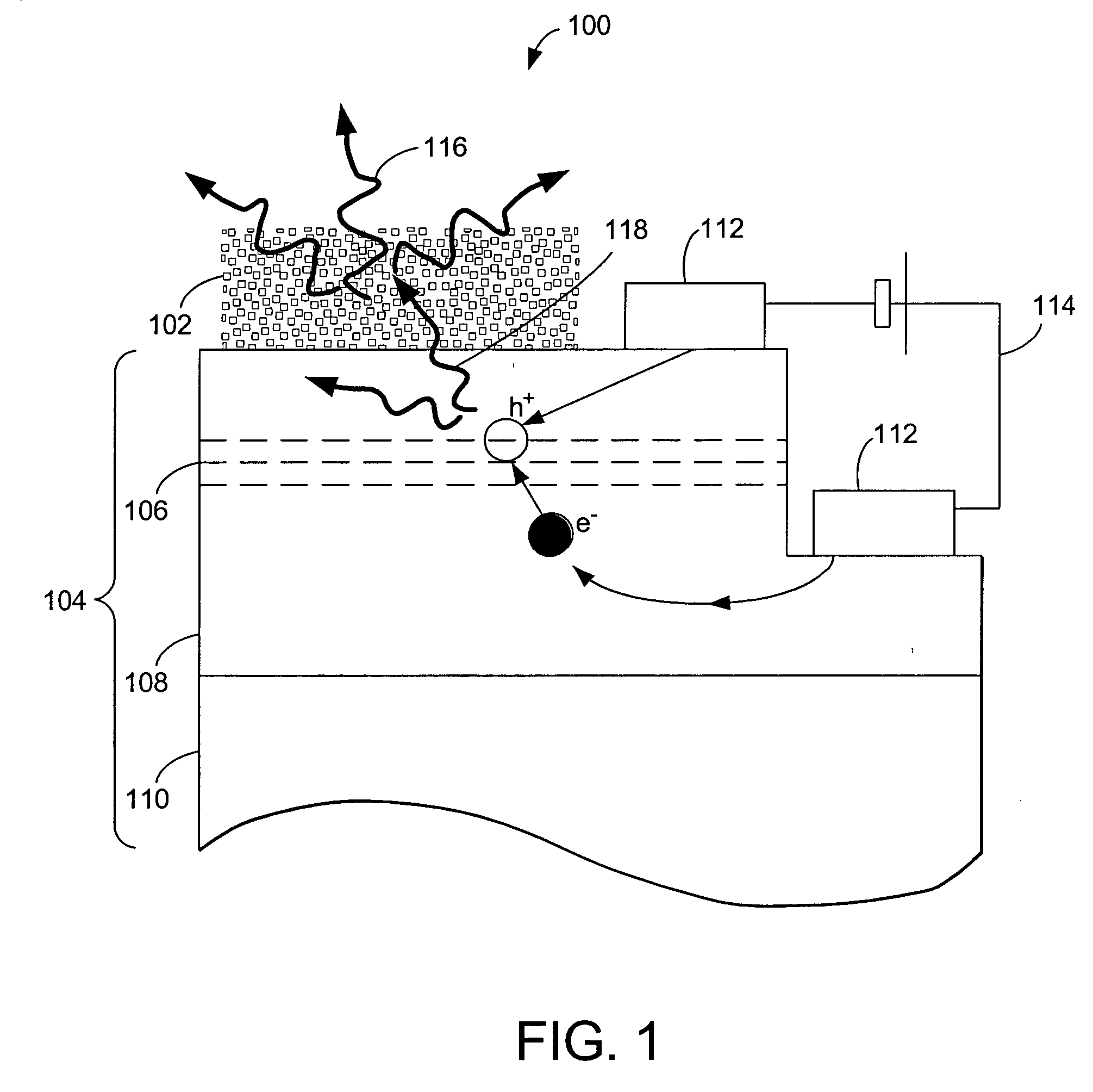
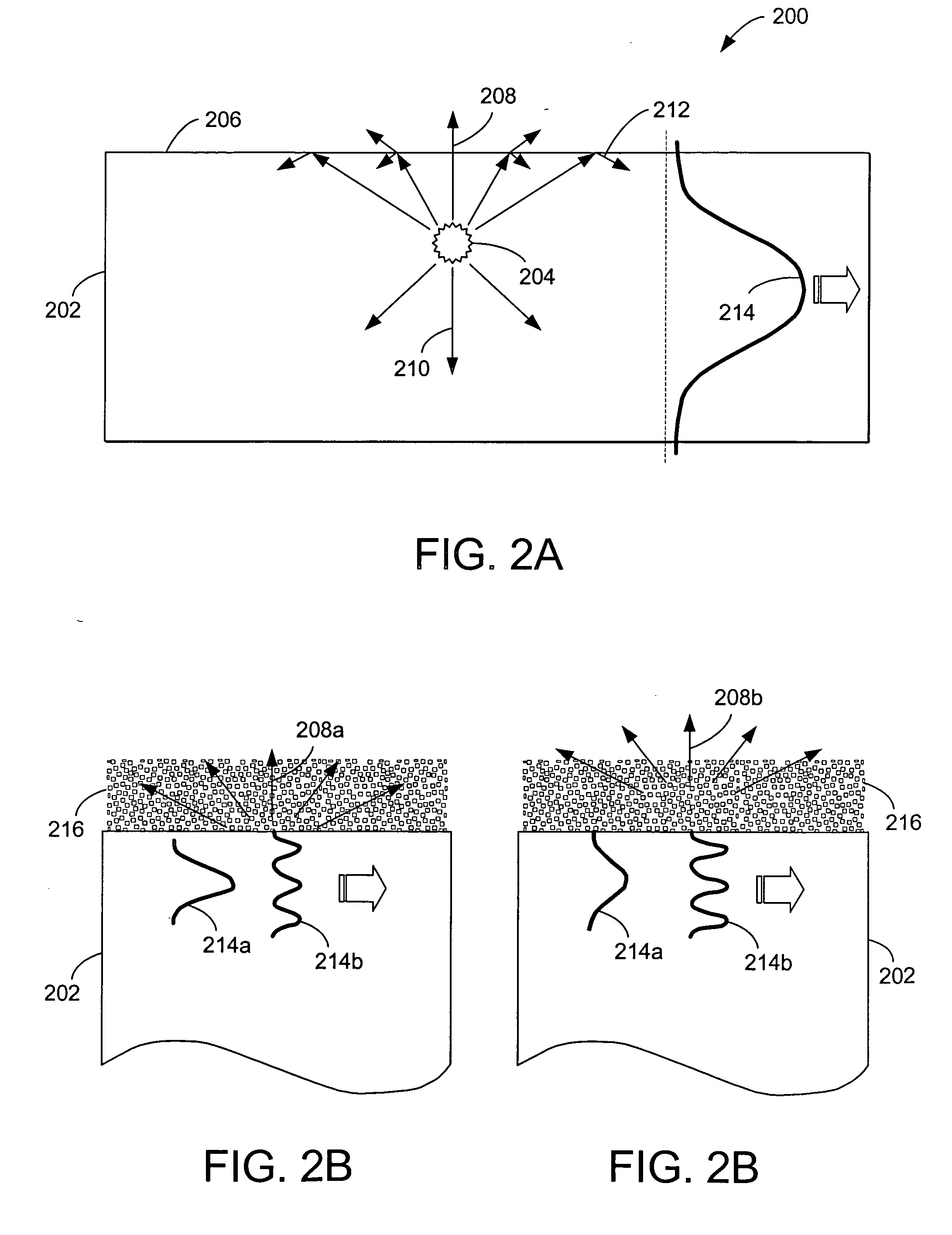
[0053] The present invention describes new multiple-light sources LEDs that provide increased light extraction and conversion efficiencies, as well as increased brightness, while retaining planar structures. The LEDs contain several emitting species, each providing light emission in a range of wavelengths. Some of the species are electrically-pumped, while other species are optically-pumped. Photonic crystals, acting as diffraction gratings, ensure efficient light extraction, efficient excitation of the optically-pumped species, and / or provide with a means for modifying the far-...


PUM


Abstract

A high efficiency light emitting diode (LED) comprised of a substrate, a buffer layer grown on the substrate (if such a layer is needed), a first active region comprising primary emitting species (PES) that are electrically-injected, a second active region comprising secondary emitting species (SES) that are optically-pumped by the light emitted from the PES, and photonic crystals, wherein the photonic crystals act as diffraction gratings to provide high light extraction efficiency, to provide efficient excitation of the SES, and/or to modulate the far-field emission pattern.

Description

CROSS-REFERENCE TO RELATED APPLICATIONS [0001] This application is related to the following co-pending and commonly-assigned applications: [0002] U.S. utility application Ser. No. 11 / 067,910, filed on Feb. 28, 2005, by Claude C. A. Weisbuch, Aurelien J. F. David, James S. Speck, and Steven P. DenBaars, entitled “SINGLE OR MULTI-COLOR HIGH EFFICIENCY LIGHT EMITTING DIODE (LED) BY GROWTH OVER A PATTERNED SUBSTRATE,” attorneys' docket number 30794.122-US-01 (2005-145-1); [0003] U.S. utility application Ser. No. 11 / 067,956, filed on Feb. 28, 2005, by Claude C. A. Weisbuch, Aurelien J. F. David, and Steven P. DenBaars, entitled “HIGH EFFICIENCY LIGHT EMITTING DIODE (LED) WITH OPTIMIZED PHOTONIC CRYSTAL EXTRACTOR,” attorneys' docket number 30794.126-US-01 (2005-198-1); [0004] U.S. utility application Ser. No. 11 / 067,957, filed on Feb. 28, 2005, by Claude C. A. Weisbuch, Aurelien J. F. David, James S. Speck, and Steven P. DenBaars, entitled “HORIZONTAL EMITTING, VERTICAL EMITTING, BEAM SHA...

Claims


Application Information

Patent Timeline
IPC IPC(8): H01L33/00H01L33/20H01L33/50
CPCB82Y20/00G02B2006/1213H01L33/20H01L33/502H01L2933/0083
Inventor DIANA, FREDERIC S.DAVID, AURELIEN J.F.PETROFF, PIERRE M.WEISBUCH, CLAUDE C.A.
Owner RGT UNIV OF CALIFORNIA
Why Eureka
Try Eureka