Trigger signal generator

Inactive Publication Date: 2007-04-19
YOKOGAWA ELECTRIC CORP
View PDF1 Cites 8 Cited by
  • Summary
  • Abstract
  • Description
  • Claims
  • Application Information

AI Technical Summary

Benefits of technology

[0027] Accordingly, the frequency detector circuit performs frequency detection by the frequency-divided signal having low frequency. Therefore, the frequency detector circuit can be constructed with a circuit that can be implemented easier than the configuration that detects the high-frequency input signal, and also a cost can be suppressed low.
[0033] Accordingly, the delaying section delays the frequency-divided signal for a predetermined period and outputs the delayed signal to the synchronizer. Therefore, for example, generation of the meta-stable can be suppressed and the trigger signal of good waveform quality can be output.
[0036] Accordingly, the waveform shaper speeds up a rising edge and a falling edge of the frequency-divided signal. Therefore, generation of the meta-stable can be suppressed and the trigger signal of good waveform quality can be output.
[0039] Accordingly, the amplitude adjusting section adjusts the amplitude of the input signal. Since the input signal whose amplitude is controlled is input into the frequency divider circuit and the synchronizing circuit, the frequency divider circuit and the synchronizing circuit can be operated optimally and stably. Therefore, the jitter generated in the frequency divider circuit and the synchronizing circuit can be suppressed further. As a result, the trigger signal that is in synchronization with the input signal and contains few jitters can be generated.
[0041] Accordingly, the waveform measuring device performs the sampling of the measured signal by the trigger signal having few jitters. Therefore, the measured signal can be measured with high accuracy.

Problems solved by technology

As a result, it is difficult to execute the sampling of the measured signal with good accuracy.

Method used


Image

  • Trigger signal generator
  • Trigger signal generator
  • Trigger signal generator

Examples


first embodiment

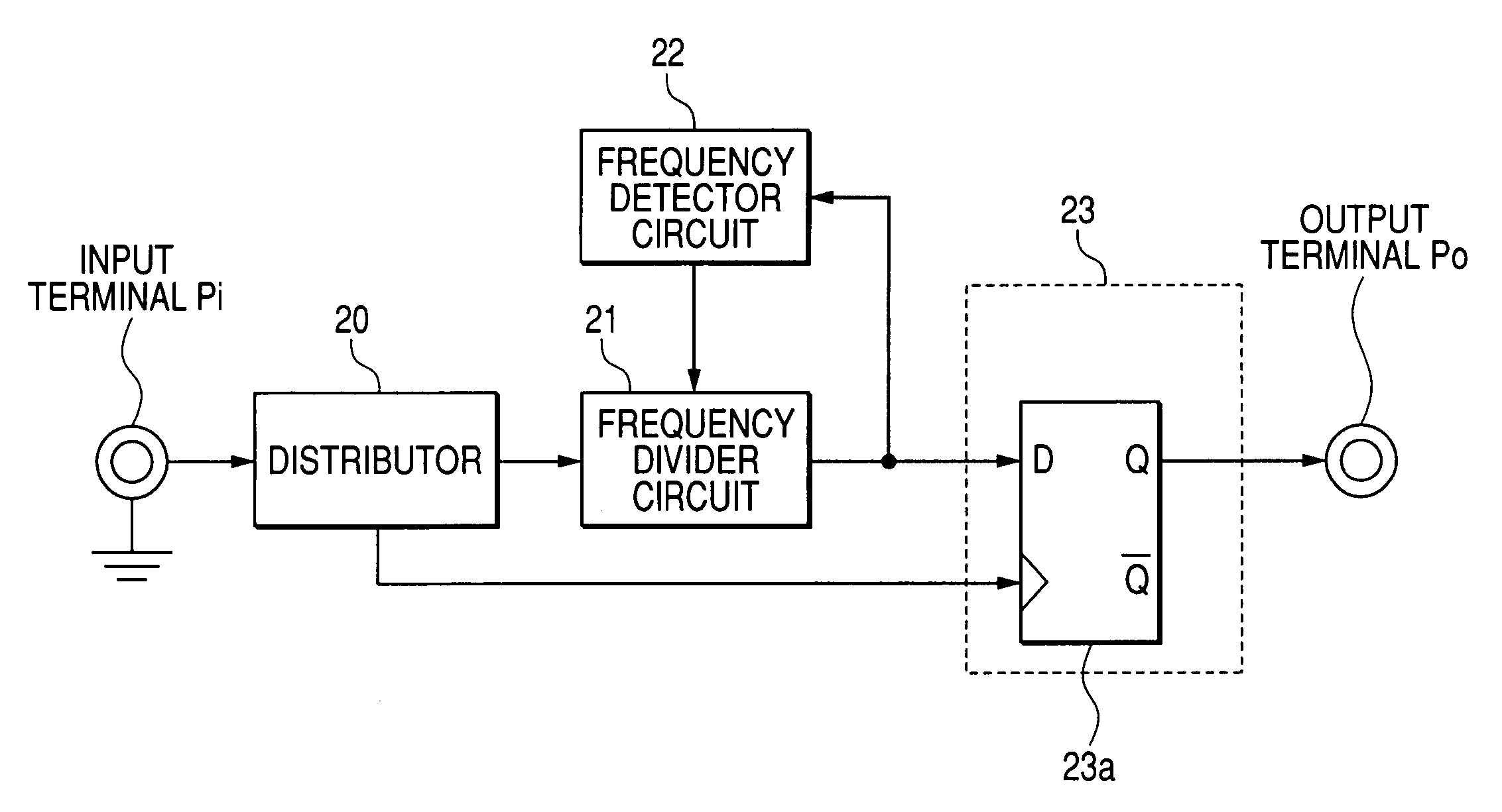
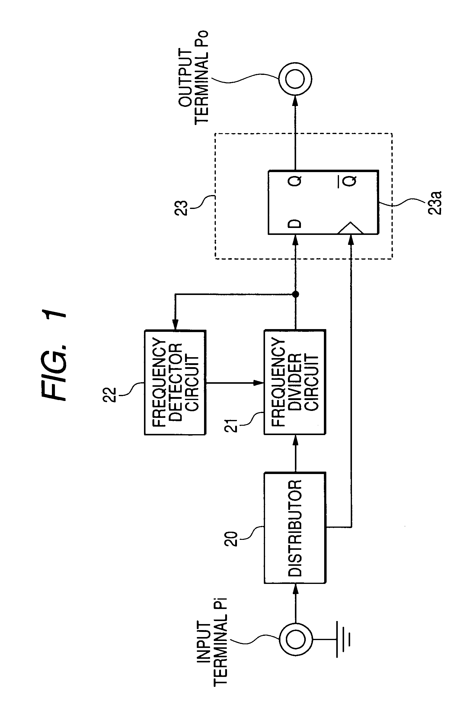
[0051]FIG. 1 is a configurative view showing a first embodiment of the present invention. Here, the same reference symbols are affixed to the same sections as those in FIG. 7 and their explanation will be omitted herein. In FIG. 1, a distributor 20 receives the input signal at its input terminal Pi, and branches the input signal into two parts and outputs them. A frequency divider circuit 21 receives one of the signals branched by the distributor 20, and divides the frequency of the input signal and outputs it. A frequency detector circuit 22 receives the signal whose frequency is divided by the frequency divider circuit 21, then detects the frequency of the input signal, and then controls a dividing ratio of the frequency divider circuit 21.

[0052] A synchronizing circuit 23 has a D-type flip-flop (abbreviated as DFF (Delay flip-flop) hereinafter) 23a. The synchronizing circuit 23 receives the signal whose frequency is divided from the frequency divider circuit 21 and also receives...

second embodiment

[0064]FIG. 3 is a configurative view showing a second embodiment of the present invention. Here, the same reference symbols are affixed to the same sections as those in FIG. 1 and their explanation will be omitted herein, and also illustrations other than the synchronizing circuit 23 are omitted herein. In FIG. 3, a variable delaying section 23b is newly provided to the synchronizing circuit 23. The variable delaying section 23b is provided between the frequency divider circuit 21 and the data input terminal of the DFF 23a. The variable delaying section 23b causes the frequency-divided signal from the frequency divider circuit 21 to delay by a predetermined period and outputs the delayed signal to the data input terminal of the DFF 23a.

[0065] An operation of such generator will be explained hereunder. FIG. 4 is a timing chart showing the operation of the equipment shown in FIG. 3. Here, explanation of the same sections as those in FIG. 2B will be omitted herein. FIG. 4 shows in ord...

third embodiment

[0070]FIG. 5 is a configurative view showing a third embodiment of the present invention. Here, the same reference symbols are affixed to the same sections as those in FIG. 3 and thus their explanation will be omitted herein, and also illustrations other than the synchronizing circuit 23 are omitted herein. In FIG. 5, a waveform shaper 23c is newly provided to the synchronizing circuit 23. The waveform shaper 23c is provided between the frequency divider circuit 21 and the variable delaying section 23b. The waveform shaper 23c applies a waveform shaping to the frequency-divided signal fed from the frequency divider circuit 21, and outputs a resultant signal to the variable delaying section 23b.

[0071] An operation of such generator will be explained hereunder. A delay is generated in the frequency divider circuit 21. In this case, when the waveform is deteriorated further and thus the rising edge and the falling edge are rounded (i.e., a rise time from a low level to a high level an...


PUM


Abstract

A trigger signal generator for outputting a trigger signal having a lower frequency than that of an input signal, the trigger signal generator including: a frequency divider circuit for dividing a frequency of the input signal; and a synchronizing circuit including a synchronizer for synchronizing the frequency-divided signal with the input signal.

Description

[0001] This application claims foreign priority based on Japanese Patent Application No. 2005-303341, filed Oct. 18, 2005, the content of which is incorporated herein by reference in its entirety. BACKGROUND OF THE INVENTION [0002] 1. Field of the Invention [0003] The present invention relates to a trigger signal generator for outputting a trigger signal whose frequency is lower than that of an input signal, and more particularly, to a trigger signal generator for generating a trigger signal that is in synchronization with the input signal and contains few jitters. [0004] 2. Description of the Related Art [0005] The trigger signal generator is a circuit that generates a trigger signal (also called as a strobe signal) used to detect a status change of a measured signal. The trigger signal generator is used in a sampling circuit of a waveform measuring device such as an oscilloscope. The trigger signal generator is used to generate a trigger signal to cause a sampler (circuit for conv...

Claims


Application Information

Patent Timeline
IPC IPC(8): H04N5/50
CPCG01R13/0254
Inventor FURUKAWA, OSAMU
Owner YOKOGAWA ELECTRIC CORP
Why Eureka
Try Eureka