
Rapid exchange catheter with hypotube and short exchange length

a catheter and hypotube technology, applied in balloon catheters, surgery, other medical devices, etc., can solve the problems of kinking, lack of pushability, and inability to meet the needs of the distal flexible portion of the catheter, so as to increase the distal flexibility of the catheter, and increase the distal flexibility

Inactive Publication Date: 2007-04-19
INNOVATIONAL HLDG LLC
View PDF2 Cites 33 Cited by
  • Summary
  • Abstract
  • Description
  • Claims
  • Application Information

AI Technical Summary

Benefits of technology

[0011] According to another aspect of the invention, a balloon catheter is comprised of a stainless steel proximal hypotube, a nickel titanium distal hypotube connected to the proximal hypotube, a cut portion at a distal end of the nickel titanium distal hypotube which provides increased distal flexibility of the catheter and an expandable balloon connected to the distal end of the nickel titanium hypotube. A distance between the spiral cut portion and the balloon is about 40 mm or less.
[0012] According to a further aspect of the invention, a balloon catheter is comprised of a stainless steel proximal hypotube, a nickel titanium distal hypotube connected to the proximal hypotube, a cut portion at a distal end of the nickel titanium distal hypotube which provides increased distal flexibility of the catheter and an expandable balloon connected to the distal end of the nickel titanium hypotube. A distance between the spiral cut portion and the balloon is about 40 mm or less.
[0013] According to another aspect of the invention, a balloon catheter is comprised of a nickel titanium hypotube having a cut distal end for increased distal flexibility, a polymer jacket surrounding the cut distal end and an expandable balloon connected to the distal end of the nickel titanium hypotube. A distance between the laser cut distal end and the balloon is about 40 mm or less.

Problems solved by technology

However, the hypotubes and wires which have been used do not have the flexibility required for the distal flexible portion of the catheter.
The Bonzel catheter has drawbacks, however, including the lack of guidewire support of the distal portion of the catheter shaft resulting in possibilities of kinking and lack of pushability.

Method used


Image

  • Rapid exchange catheter with hypotube and short exchange length
  • Rapid exchange catheter with hypotube and short exchange length
  • Rapid exchange catheter with hypotube and short exchange length

Examples


Embodiment Construction

[0025] Referring to the drawing figures, like reference numerals designate identical or corresponding elements throughout the several figures.

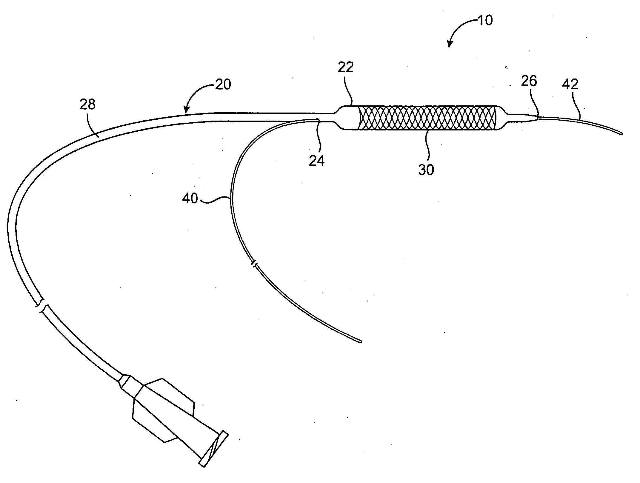
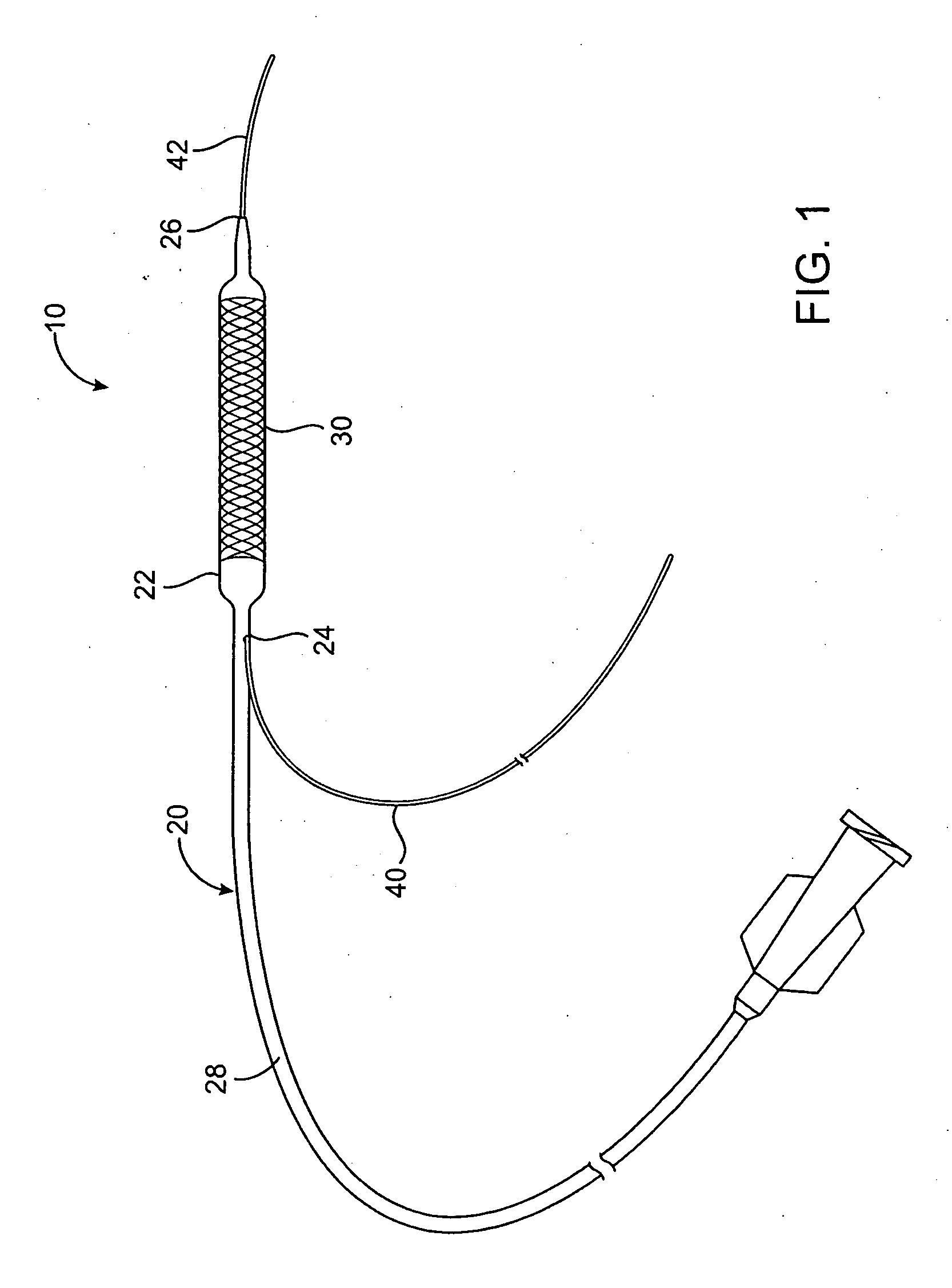
[0026] A catheter system 10 illustrated in FIG. 1 embodies principles of the present invention, and includes a catheter 20 (shown schematically), which is optionally a rapid exchange angioplasty balloon catheter, a stent 30, and a guidewire 40. FIG. 1 illustrates the catheter 20 including an expandable balloon 22, with the balloon in an expanded or inflated configuration. In an unexpanded or delivery configuration, the balloon 22 and stent 30 will have an outer diameter close to the outer diameter of the shaft 28 of the catheter 20. As illustrated in FIG. 1, the catheter 20 includes a distal guidewire port 26 at a distal end of the catheter and a proximal guidewire port 24 proximal of balloon 22. According to an exemplary use, the catheter 20 is inserted into a patient, e.g., into the vasculature of a patient, over the guidewire 40 by passing...


PUM


Abstract

A rapid exchange balloon catheter includes a short rapid exchange portion which reduces friction between the guidewire and the catheter. The catheter shaft includes one or more sections of hypotubing and overjacketing of diminishing distal flexibility by, e.g., forming cuts in the hypotubing and / or varying the jacketing material and / or thickness. A polymer jacket overlies the hypotubing, and an inner sleeve is provided adjacent to the proximal guidewire port to further strengthen the catheter shaft.

Description

BACKGROUND OF THE INVENTION [0001] 1. Field of the Invention [0002] The invention relates to interventional catheters, and more particularly to rapid exchange balloon catheters. [0003] 2. Brief Description of the Related Art [0004] Rapid exchange balloon catheters are described in U.S. Pat. Nos. 4,762,129 and 5,040,548, the entireties of which are incorporated herein by reference. These rapid exchange catheters include a distal guidewire lumen which extends through the balloon from a distal end of the balloon to a guidewire exit port that is proximal of the balloon, but which is distal of the proximal end of the catheter. In these and other known rapid exchange balloon catheter systems the catheter shafts include a proximal stiff catheter section extending along about 75% of the catheter length and a distal more flexible portion of the catheter between the stiff section and the balloon. For catheters which are designed for angioplasty or for stent delivery, the portion of the cathet...

Claims


Application Information

Patent Timeline
IPC IPC(8): A61M29/00A61M31/00A61M37/00
CPCA61M25/10A61M2025/0183A61M2025/1084
Inventor FISHER, BEAU M.BROWN, PETER S.
Owner INNOVATIONAL HLDG LLC
Learn More