Outboard motor steering control system

a steering control and outboard motor technology, applied in the direction of marine propulsion, special-purpose vessels, vessel construction, etc., can solve the problem that the boat operator is likely to experience an unnatural feeling

Inactive Publication Date: 2007-04-26
HONDA MOTOR CO LTD
View PDF3 Cites 17 Cited by
  • Summary
  • Abstract
  • Description
  • Claims
  • Application Information

AI Technical Summary

Benefits of technology

[0006] An object of this invention is therefore to overcome this inconvenience by providing an improved steering control system for an outboard motor that is equipped with an internal combustion engine and a propeller driven by the engine and is steered by operating an actuator connected to a steering shaft of the outboard motor in accordance with the turning of a steering wheel of the boat on which the outboard motor is mounted, that can eliminate a phase difference between the angles or positions of the steering wheel and the steering shaft occurred for example at engine starting, without giving the boat operator an unnatural feel.
[0007] In order to achieve the object, this invention provides a system for controlling steering an outboard motor adapted to be mounted on a stern of a boat and having an internal combustion engine that powers a propeller, comprising: a steering wheel installed at a cockpit of the boat to be turned by an operator; an actuator that rotates the outboard motor about a steering shaft in response to turning of the steering wheel such that the outboard motor is steered relative to the boat; a steering wheel angle sensor which produces an output indicative of a turned angle of the steering wheel; a rotation angle sensor which produces an output indicative of a rotation angle of the steering shaft; and a controller which compares the outputs of the steering wheel angle sensor and the rotation angle sensor to determine whether there is a phase difference in steering angle when the engine is started, controls operation of the actuator so as to eliminate the difference, if the phase difference is found, when the operator turns the steering wheel, and informs the operator of the phase difference.

Problems solved by technology

If the correction is made without taking the intention of the boat operator into account, the boat operator is likely to experience an unnatural feel.

Method used


Image

  • Outboard motor steering control system
  • Outboard motor steering control system
  • Outboard motor steering control system

Examples


first embodiment

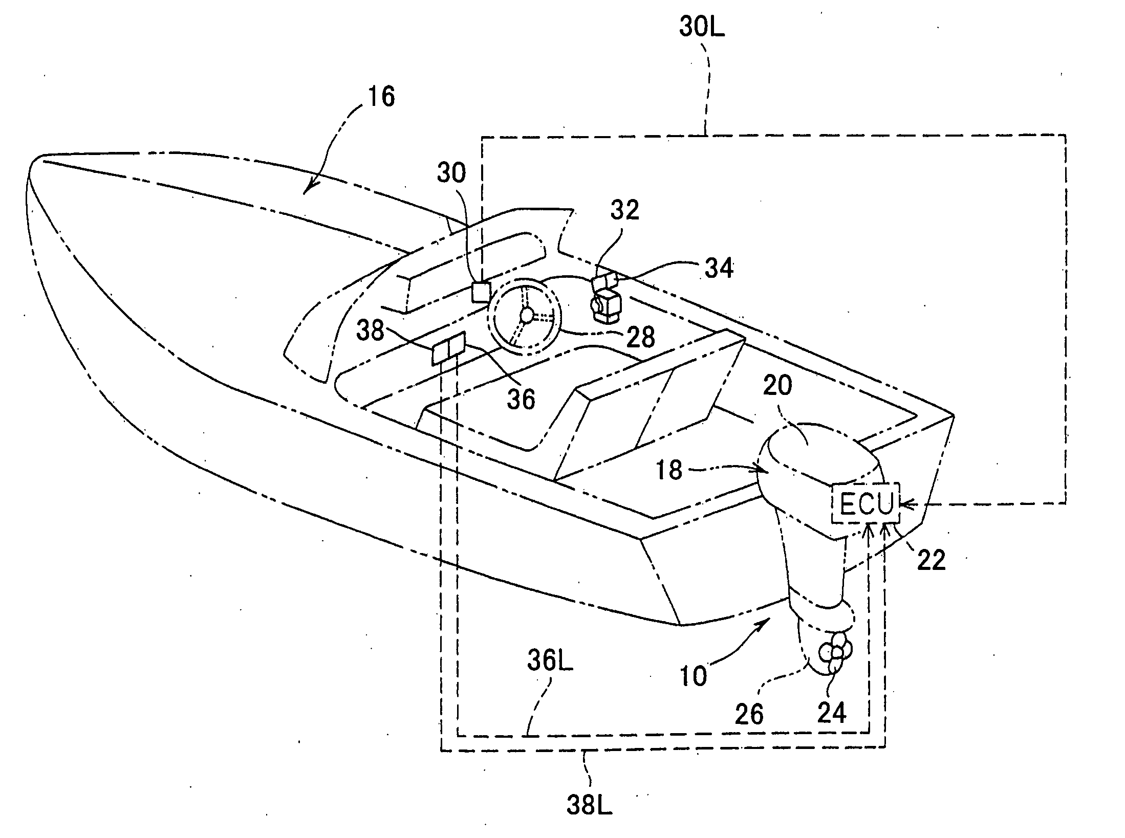
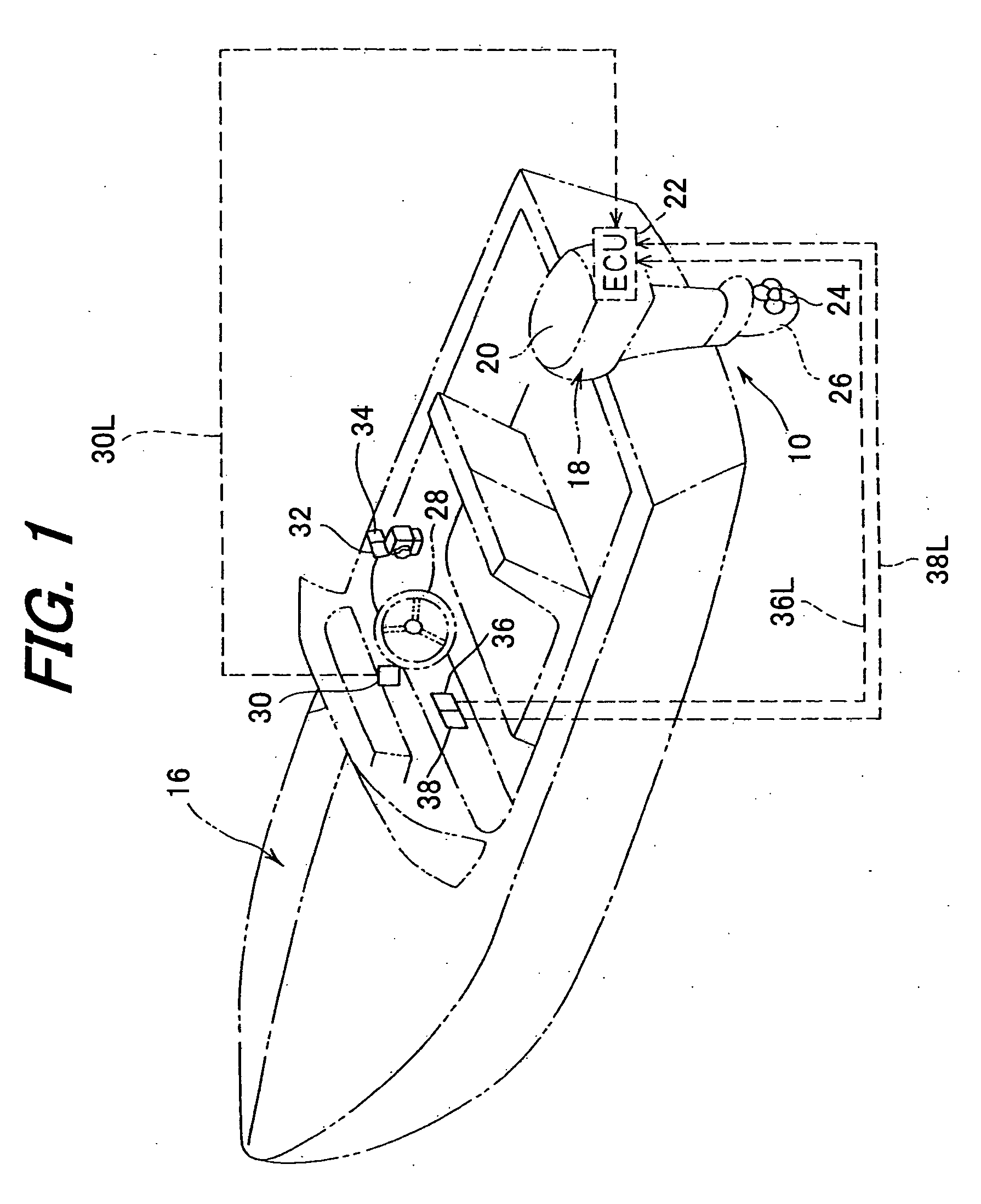
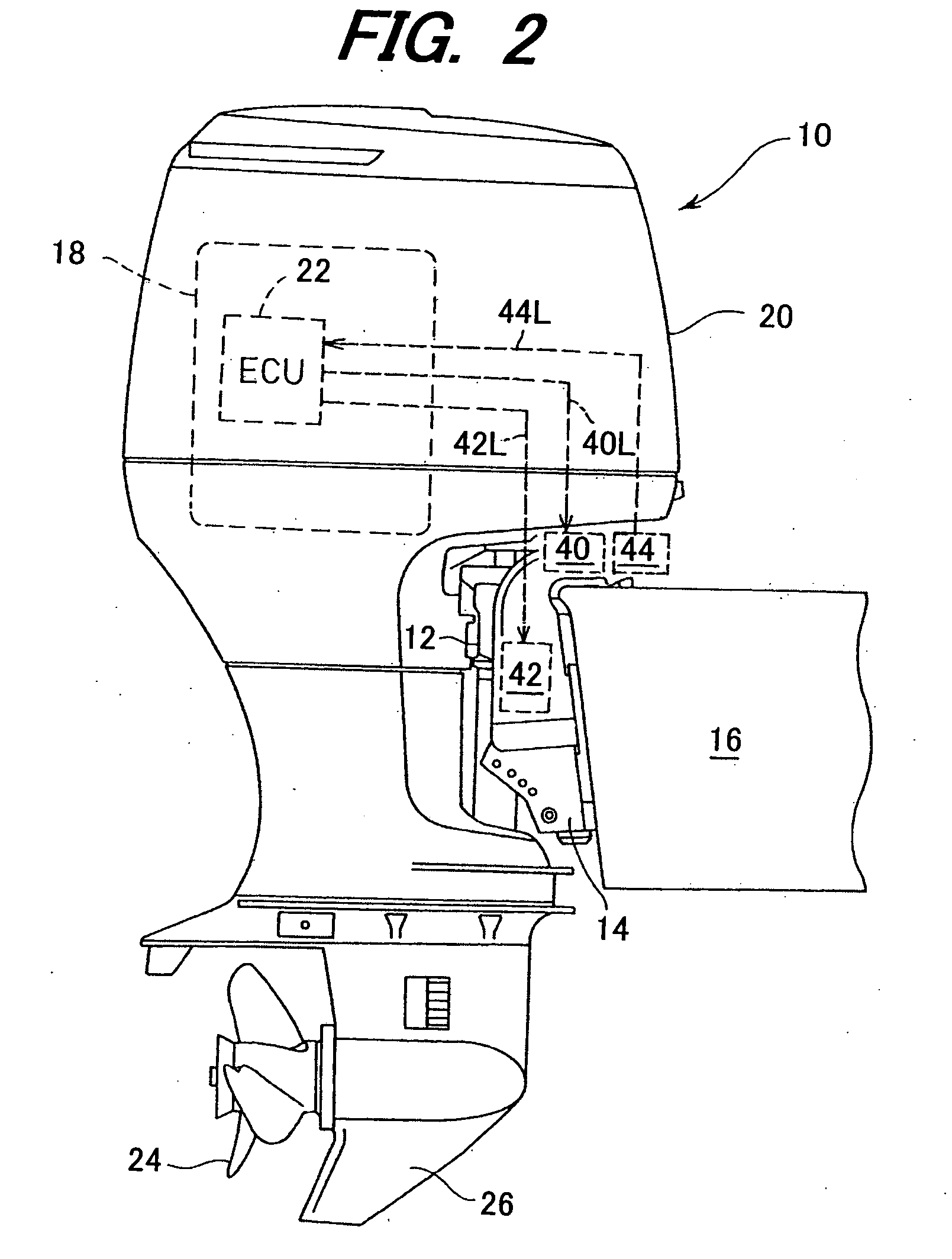
[0023]FIG. 1 is an overall schematic view of an outboard motor steering control system according to the invention and FIG. 2 is a partial side view of the system.

[0024] In FIGS. 1 and 2, reference numeral 10 indicates an outboard motor that integrally comprises an internal combustion engine, propeller shaft, propeller and the other components. As shown in FIG. 2, the outboard motor 10 is fastened to the stern of a boat or hull 16 to be freely steered about the vertical axis and horizontal axis through a swivel case 12 housing a swivel shaft (explained later) that is freely rotated therein and stern brackets 14 connected to the swivel case 16.

[0025] The internal combustion engine (hereinafter referred to as the “engine”; now assigned by reference numeral 18) is disposed at the upper portion of the outboard motor 10. The engine 18 comprises a spark-ignition, in-line, four-cylinder, four-cycle gasoline engine with a displacement of 2,200 cc. The engine 18 is located above the water su...

second embodiment

[0071]FIG. 12 are a set of views, similar to FIG. 11, showing an outboard motor steering control system according to this invention.

[0072] In the outboard motor steering control system according to the second embodiment, the indicator comprise six lamps 74c to 74h, which are also constituted as light emitting devices such as LEDs or electric bulbs.

[0073] The operation of the outboard motor steering control system according to the second embodiment will be explained.

[0074] The operation differs from that of the first embodiment in the execution of S18 of the flowchart of FIG. 8, i.e., the step in which the phase difference elimination control is performed and the boat operator is kept informed of the phase difference. Specifically, as shown in FIG. 12A, when a phase difference is present, the lamps on the side of the phase difference, the right lamps 74f, 74g, 74h in the illustrated example, are lit in a number that increases with increasing phase difference magnitude. As shown in ...

third embodiment

[0076]FIG. 13 is an explanatory view, similar to FIG. 9, showing an outboard motor steering control system according to this invention, with focus on the use of an indicator for keeping the boat operator informed.

[0077] As shown in the drawing, the dashboard at the cockpit where the steering wheel 28 is installed is ordinarily provided with a tachometer 76, speedometer (boat speed indicator) 78 and buzzer (medium of sound) 80. In the third embodiment, processing is performed in S18 of the flowchart of FIG. 9 of the first embodiment for implementing the phase difference elimination control and using the buzzer 80 to keep the boat operator continually informed of the direction and magnitude of the phase difference.

[0078] Specifically, the buzzer 80 is intermittently sounded at shorter intervals with increasing magnitude of the phase difference and is sounded at longer intervals with decreasing magnitude of the phase difference. When the phase difference is eliminated, the buzzer 80 i...


PUM


Abstract

An outboard motor steering control system operates at starting of the engine to compare the output of the steering wheel angle sensor which indicates the turned angle of the steering wheel and the output of the rotation angle sensor which indicates the rotation angle of the swivel shaft, determines whether there is a phase difference in steering angle therebetween, responds to any phase difference found by, at the time the boat operator turns the steering wheel, controlling the operation of the actuator connected to the swivel shaft so as to eliminate the difference, and further operates to inform the boat operator of the difference. Owing to this configuration, the difference can be eliminated without causing the boat operator to experience an unnatural feel.

Description

FIELD OF THE INVENTION [0001] This invention relates to an outboard motor steering control system. CROSS-REFERENCE TO RELATED APPLICATION [0002] This invention claims priority under 35 USC 119 based on Japanese Patent Application No. 2005-353979, filed on Dec. 7, 2005, the entire disclosure of which is incorporated herein by reference. DESCRIPTION OF THE RELATED ART [0003] In one common arrangement for steering an outboard motor mounted on a boat, a steering wheel installed in the boat is mechanically connected to a steering mechanism of the outboard motor through a push-pull cable or similar connecting means. When the boat operator turns the steering wheel, the rotational motion of the steering wheel is converted to linear motion that is transmitted to the steering mechanism though the push-pull cable. However, this arrangement does not offer the boat operator a constantly good steering feel because the steering load on the steering wheel varies with the size of the boat and outboa...

Claims


Application Information

Patent Timeline
Patent Type & Authority Applications(United States)
IPC IPC(8): B63H25/00G05D1/02
CPCB63H20/12B63H25/00B63H25/36B63H25/42
Inventor YAZAKI, MAKOTOOTOBE, TAIICHITAKADA, HIDEAKI
Owner HONDA MOTOR CO LTD
Why Eureka
Try Eureka