Method and apparatus for packing chromatography columns

a technology of chromatography column and packing method, which is applied in the direction of ion-exchangers, separation processes, instruments, etc., can solve the problems of reducing manufacturing throughput, affecting the quality of chromatography column, and taking as long as one hour, so as to reduce the amount of solvent and production time, reduce the amount of solvent and the effect of less complex

Active Publication Date: 2007-04-26
PHENOMENEX INC
View PDF33 Cites 33 Cited by
  • Summary
  • Abstract
  • Description
  • Claims
  • Application Information

AI Technical Summary

Benefits of technology

[0012] One aspect of the present invention relates to an improved method for the formation of economical and robust liquid chromatography columns by axial compression. Another aspect of this invention relates to a method for removing the slurry chamber while maintaining axial compression on the bed resulting in a column that is compressed but shorter and less complex than traditional axial packed columns while maintaining the flexibility to accommodate bed length variation. A further aspect of this invention significantly reduces the amount of solvent and production time required to pack the column bed compared to the slurry packing technique.
[0013] There is advantageously provided a removable slurry / pre-compression chamber. A segmented column or chamber assembly is used that includes a first segment, which is a slurry pre-compression chamber, and a second segment, which is the column chamber. The first segment serves as a slurry and pre-compression chamber to accommodate the chromatographic slurry prior to packing, and during the initial stages of compression. A piston driven by a piston rod or piston sleeve assembly moves the piston towards the fixed end of the column chamber (second segment). The piston itself passes through the first segment and enters the second segment. The piston travels a short distance into the second segment until the media has been adequately compressed to form a stationary bed. The design allows the slurry pre-compression chamber (first segment) to be removed while the piston rod or piston sleeve applies force to the piston to maintain the bed compression. A securing mechanism can then be attached to secure the piston in place, allowing the piston rod to be detached from the piston and removed. The ability to pack by axial compression, and then remove the slurry chamber while keeping the piston in place provides very desirable advantages.
[0014] The design also advantageously allows for small variations in final column bed length. A bed compression screw and a V-band clamp design provide fine adjustment of the piston position based on the final bed height achieved when the media is packed into the column. This ability to accommodate variable bed heights ensures that a set compression force can be maintained while accommodating variations (preferably small variations) in the amount of media packed in a column. A variation of up to about one inch (25 mm) in bed height is believed achievable with a given column length.
[0015] A two-stepped, hat shaped frit design is also advantageously provided. The frit design increases the amount of the column bed surface area covered by frit allowing quicker dispersion of the sample across the column bed. Older axial compression designs use a piston seal to engage the column wall and the frit was smaller in diameter than the column bed. The older design leaves an area between piston assembly and the wall that was not available for separations. The two-stepped, hat-shaped frit design is very useful for short bed length columns where the sample must be dispersed across the media as quickly as possible. This frit design is also believed to provide advantages for longer length columns.
[0016] There is also provided a mechanism and method for maintaining axial compression on the column bed while the slurry chamber is removed and replaced by a bed compression mechanism, such as a screw. Advantageously, the column bed is not allowed to relax or expand after packing. The compacted bed is compressed once during the packing process and this pressure is maintained when the inlet end fitting is attached. This avoids the need for springs to maintain the bed compression.
[0017] In one aspect of this invention there is provided a portable tubular chromatography column having a tubular body with an inner diameter with first and second ends covered by first and second end caps, respectively. The column has a bed of chromatographic media placed between a first and second frit all located inside the body. A piston abuts the first frit and exerts a predetermined pressure on the bed. An adjustable locking mechanism has a support fastened to the body and has a threaded adjuster interposed between the support and the piston such that rotation of the threaded adjuster increases or decreases the force the piston exerts on the bed.

Problems solved by technology

The slurry technique requires high-pressure pumps to provide the liquid flow until the bed is packed, which may take as long as one hour.
This relatively long packing time at high flow significantly increases cost of the final column due to large volume of solvent required, and reduces manufacturing throughput.
Another major disadvantage with this high pressure high flow rate slurry packing technique is that the chromatographic media is subjected to very high pressures during the packing process to form the compressed chromatographic bed but this pressure must be released when the column is removed from the slurry chamber.
This variation and reduction in bed density creates performance problems such as settling or voiding of the bed, particularly when the column is operated under high flow rates.
Currently users in high throughput, high volume preparative applications experience reduced lifetimes with columns prepared using this slurry technique, especially when the column lengths are short due to the lower density beds.
Furthermore, as the packing system and column are integrated into a single unit, cost and complexity are also higher.
But even this system requires a relatively long column tube, even if the desired bed length may be only ⅓ to ¼ that of the overall column length.
Thus the design suffers from long and sometime very heavy column assemblies that are inconvenient, impractical and difficult for operators to use in a typical laboratory or purification lab.
These designs are especially impractical in high-throughput purification laboratories where 4-8 columns may be run in parallel, and / or where space is limited.
Furthermore, the high cost of the column hardware of this longer and more complex design limits their acceptance in high use or high-throughput environments as they become too costly to operate in large numbers.
Yet another disadvantage of some axial packed columns is that the frit diameter is much smaller than the column diameter.
The older design leaves an area between piston assembly and the wall that was not available for separations.
Advantageously, the column bed is not allowed to relax or expand after packing.

Method used


Image

  • Method and apparatus for packing chromatography columns
  • Method and apparatus for packing chromatography columns
  • Method and apparatus for packing chromatography columns

Examples


first embodiment

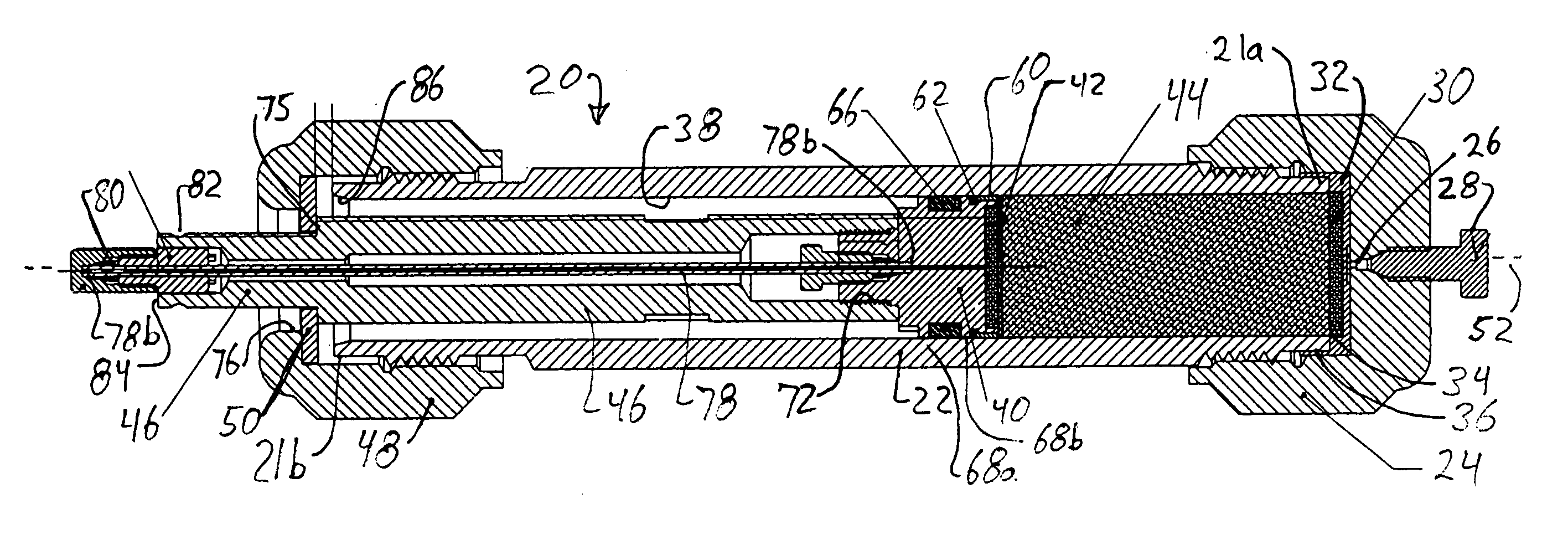
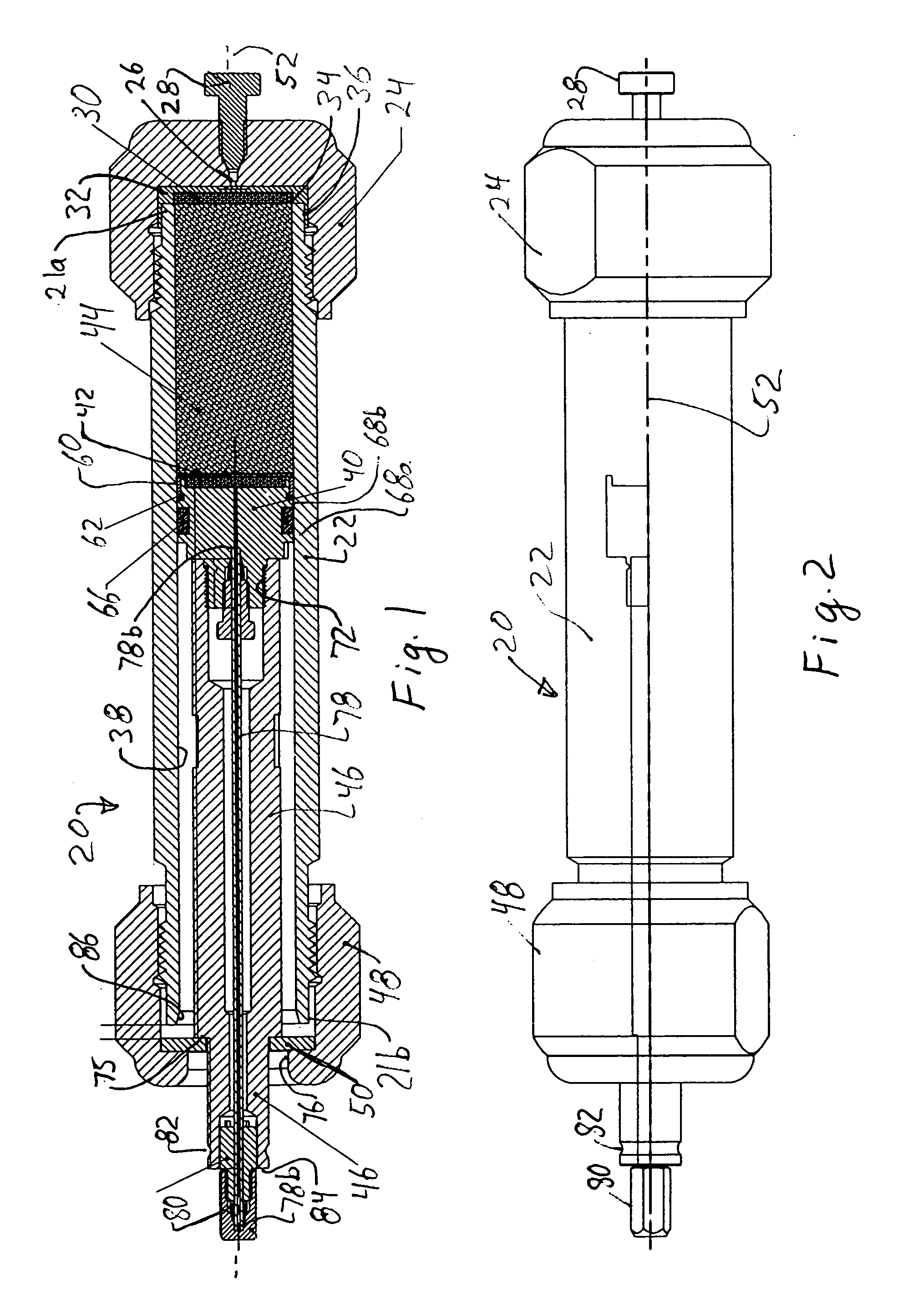
[0072] This first embodiment achieves a uniform hydraulic packing of the media 44 by piston 40 which is desirable for uniform flow of mobile phases passing through the stationary bed formed by the compacted media 44. But this embodiment requires a long body 22 and a long sleeve 46 which make the end column heavy, and which requires more material than desired. The body 22, sleeve, end caps 24, 48 are made of metal, typically stainless steel, and that material is not only heavy, but expensive. It is thus desirable to reduce the length of body 22 and eliminate, if possible, piston sleeve 46.

second embodiment

[0073] Referring to FIGS. 7-10, a second embodiment is described which uses the same piston 40 described above, but which uses a segmented body 122. For parts that are not changed the part numbers are not altered and are the description is not repeated.

[0074] The body 122 is formed of two parts, a removable, upstream tube 122a and a remaining downstream tube 122b. Both parts 122a, 122b are used for packing while removable tube 122a is removed for use, as described later in more detail. The upstream tube 122a forms a slurry chamber, while the downstream tube 122b forms the column. Tubes 122a, 122b are releasably joined by a removable, V-Band clamp. An optional wrenching surface 133 can be provided on the outside of body 122.

[0075] The slurry tube 122b has a length sufficient to hold the desired slurry media 44 prior to the media being packed. Preferably, but optionally, the length is also sufficient to accommodate at least a portion of piston 40. The upstream end 124 of column 122b ...


PUM


Abstract

A slurry chamber is fastened to and held in coaxial alignment with a chromatography column by a V-band. One end of the column has an end cap and frit. A slurry of fluid and chromatographic media is placed in the column and chamber. A piston is forced through the chamber and into the column by a hydraulic ram to expel the fluid and form a media bed in the column. The slurry chamber is removed, and a split end cap is fastened to the column. A threaded recess in the split end cap receives a split, threaded collet. The collet is tightened until it pushes against the piston with the same force as the ram, at which point the ram is released and the column removed for use.

Description

BACKGROUND OF THE INVENTION [0001] This application relates to a method apparatus for packing tubular columns with particles, such as packing HPLC columns with media. [0002] Liquid Chromatography is a method for the separation of compounds from a mixture by encouraging a different distribution between the solid particles in the stationary phase of a column and the liquid phase that is passed through the column. The column packing material needs to be well packed and uniformly packed to provide a consistent surface for the separations to occur. Depending on the individual compounds affinity for the column packing material compared to the affinity for the liquid passing through the column determines the difference in time that the compounds reside inside the column. After the compounds exit the column, they are either detected (analytical liquid chromatography) or the compounds are individually collected (preparative liquid chromatography). For the chromatographic separations to be ca...

Claims


Application Information

Patent Timeline
Patent Type & Authority Applications(United States)
IPC IPC(8): B01D15/08
CPCB01D15/206B01D15/22G01N30/56G01N30/6021G01N30/603G01N2030/522G01N2030/565
Inventor RAHN, PETER C.MAIEFSKI, ROMAINE R.FARKAS, TIVADARWELCH, EMMET E.
Owner PHENOMENEX INC
Why Eureka
Try Eureka